After moving things around and building test circuits for just about forever, I think I've finally got a layout I can live with.
I suppose I should put the binary files on GitHub or something.
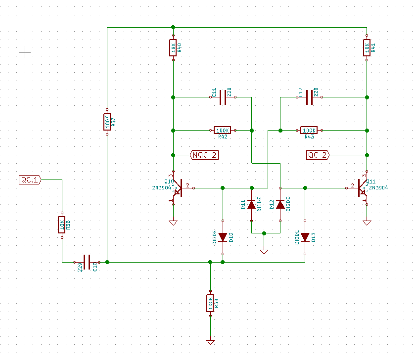
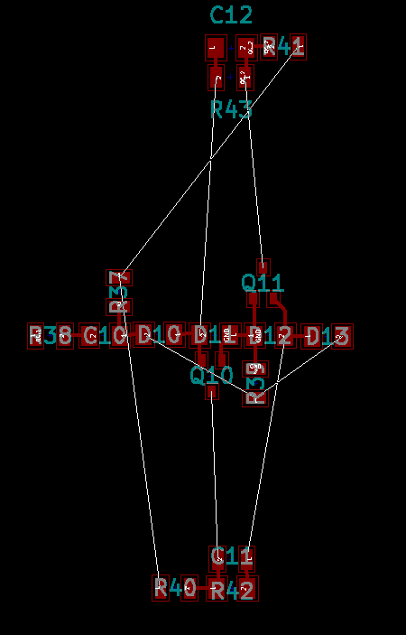
In the mean time, here's the schematic and layout for one flipflop.

The white lines are "air" wired that will be magnet wire. They are things like ground +9V0 and some other signals that I couldn't get routed perfectly. I also will wire up an input signal and two output signals.

I like having the central "spine" of 10 parts and the two "leave" segments of three parts each separated by wires.
When I connected them all together "hard" the unit was too fragile.
I'm going to rig up a wire structure that I can glue the three parts to to hold them together securely.
That's the next step.
 Alan Kilian
Discussions
Become a Hackaday.io Member
Create an account to leave a comment. Already have an account? Log In.