 ccates
Feb. 7, 2015
Daktronics Prostar 16x16 Panel Inspection
I recently came across some surplus Daktronics Prostar 16x16 RGB electronic sign panels. Unfortunately the controller was not available. hey looked interesting so I bought a several to play with. I thought they would make a great toy if I could reverse engineer them and make them work with an Arduino.
Inspection
It appears that these units were taken from a roadside electronic billboard. There are many electronic signs in the area where they were found and I suspect that these units came from a sign that was being replaced.
The units are 14 1/4 " by 14 1/4" The front has 256 LED pixels arranged on a 16 x 16 Grid.
Each pixel has a red LED, a green LED and a blue LED making a total of 768 LEDs.
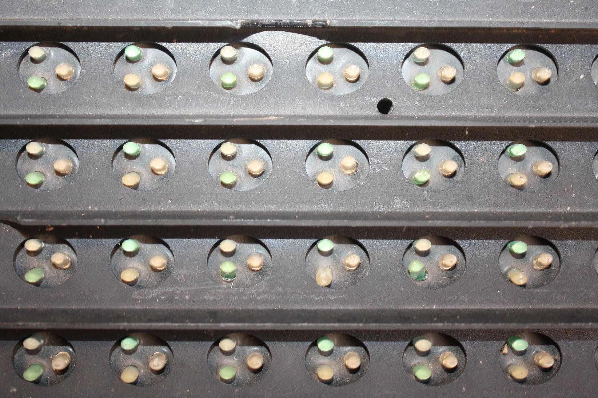
There is a shadow mask of plastic on the front that helps the display be seen in bright daylight. Behind the shadow mask is the circuit board embedded in a 3/8" layer of silicone.
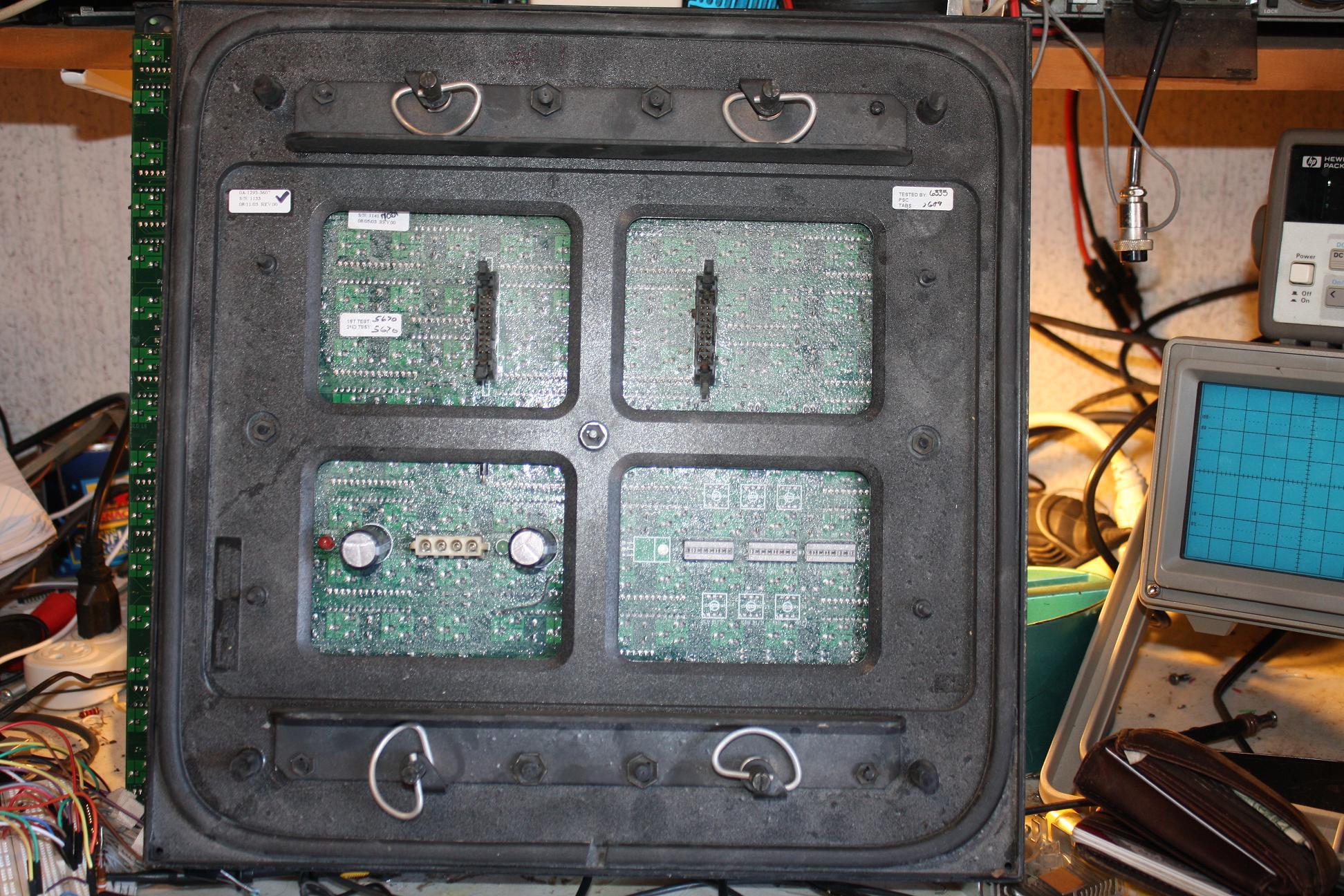
The back of the unit is plastic and has two L shaped metal mounting brackets. These were used to mount the unit to a frame. Two units could be mounted back to back producing a two sided sign when mounted in the frame. The back has a seal around the edges that seals to the frame and helps waterproof the unit.
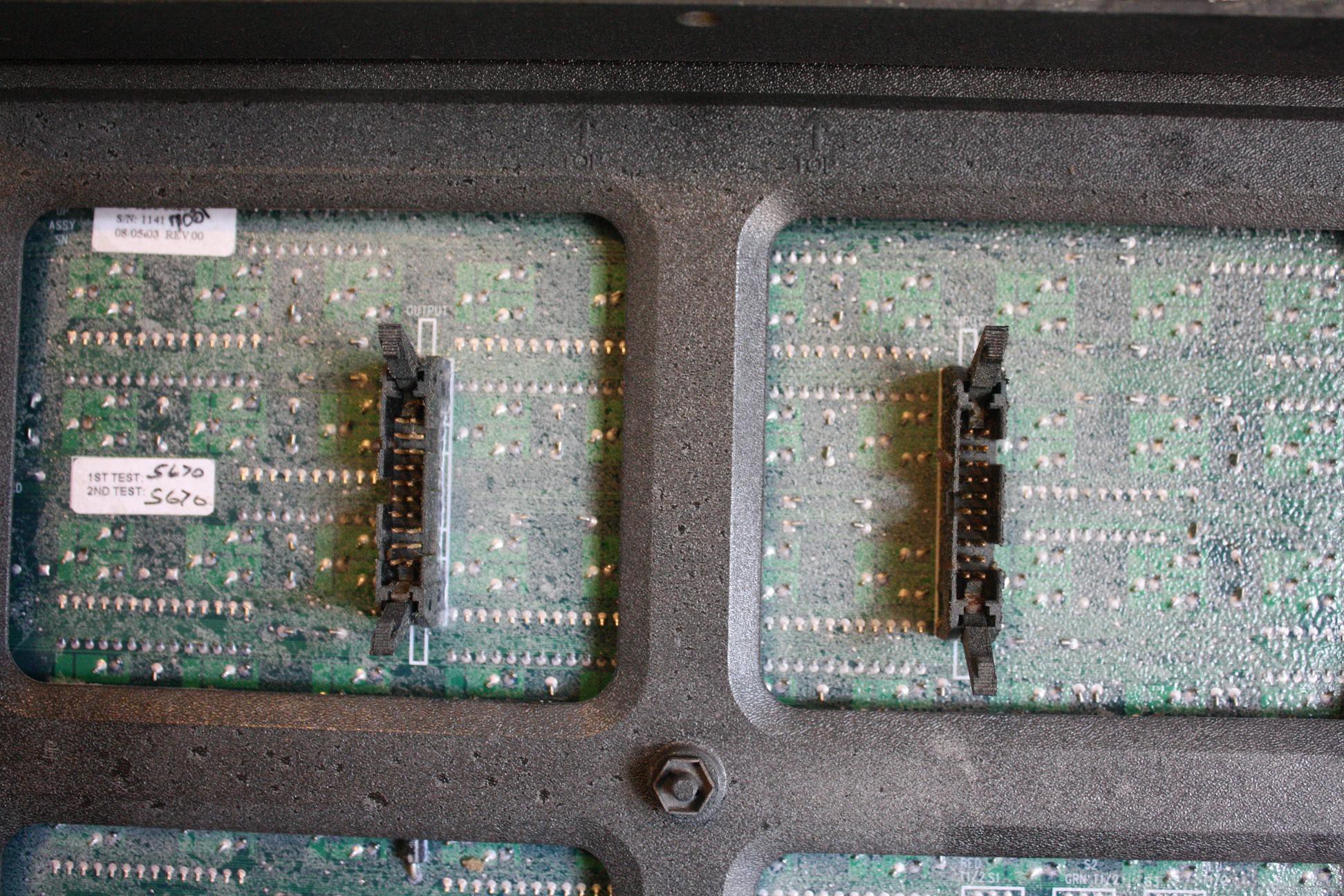
On the back there are 2 - 20pin connectors - on for input and one for output. This implies that the units were daisy-chained together in the original sign.
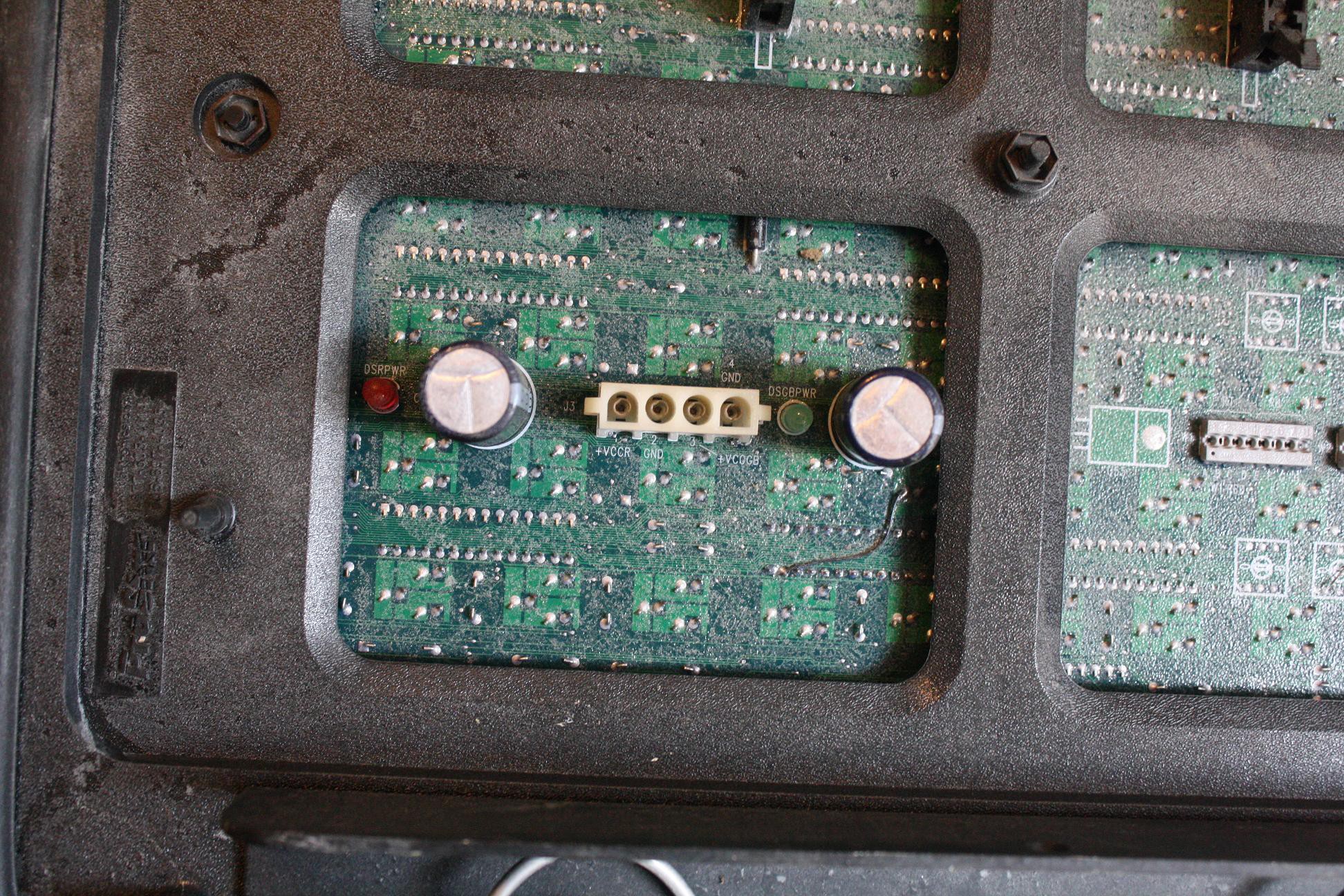
Also on the back is a power connector and two status LEDs. The power connector is labeled +VCCR, GND, +VCCGB, GRN. It appears to be a female molex connector. The separate supply input implies that a different supply was used for the RED and GREEN/BLUE circuitry.
On the right of the power supply connector is a set of three 8 position punchout jumpers. They are labeled RT-RB GT-GB BT-BB at the top and W1RED, W2GRN, W3BLUE at the bottom.
Next step - Teardown
Discussions
Become a Hackaday.io Member
Create an account to leave a comment. Already have an account? Log In.