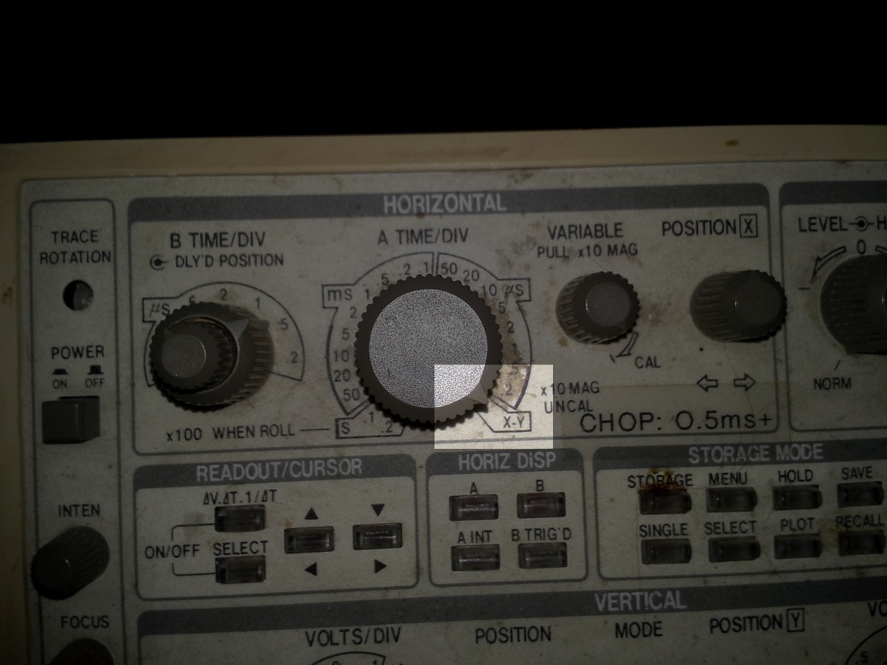
This experiment/learning-experience began as my not-so-uncommon accidental-switch to "x-y mode" while trying to zoom in on a brief signal beyond my 'scope's time-scale zoom-ability.

(Obviously, I need to get out the ol' rubbing-alcohol and cotton-swabs!)
I needed to determine the time-delay between the rising/falling-edges of two signals.

Even at maximum-zoom (0.2us/div), these signals appear to be nearly-simultaneous.
I had imagined they should be; these two outputs are two bits on the same port, toggled simultaneously by the same port-write instruction in my microcontroller (an ATmega8515).
e.g.:
while(1)
{
   PORTE = 0x03;
   PORTE = 0x00;
}
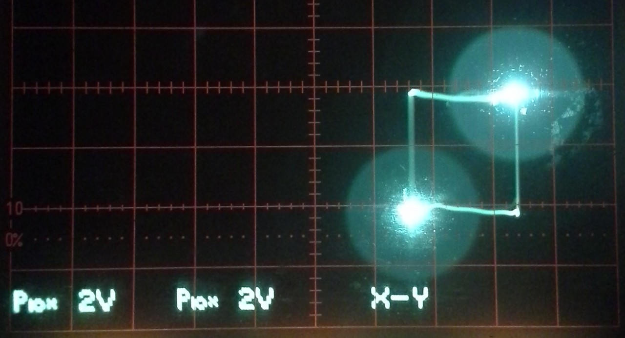
The two channels on the oscilloscope are connected to port output pins PE0 and PE1 (bits 0 and 1 on port 'E').After "over-zooming" into X-Y Mode, I saw the following:

And immediately noticed that *if* the two signals were, in fact, simultaneous, then I should've gotten the two bright dots at the lower-left and upper-right corners, and a straight-ish line between these two points; the graph of y=x (where x is from 0V to 3.6V)... (or maybe a skinny slanted diamond/trapezoid?)
Instead, we're seeing nearly a square.
(NOTE: It just occurred to me that I have two different brands/quality of 'scope probes, which *may* have some bearing on this? The remainder of my discussion will most-likely disregard this new tidbit... until later?)
I also noticed some other characteristics that seem to stand-out:
- [1] The very bright dots at the lower-left and upper-right corners
- [2] The "Square" connecting these two dots
- [3] The "Horizontal" lines appear to be *brighter* than the verticals
- [4] The other corners seem to be significantly "brighter" than the lines, almost a *dot*
- ([5] I didn't notice that the "horizontals" were actually as slanted as they are... this, too, will likely be disregarded early in this discussion...)
It got me to thinking what might *cause* these sorts of effects...?
Before reading-on, know that:
I'm not claiming that my hypotheses--nor even my observations--are *correct*.
As I said before, I've barely ever used the X-Y mode for anything other than some entry-level analog "labs" nearly a decade ago... This is *hypothesizing* and *experimenting*, and some of my observations seem to be corroborated by some loose-interpretation of the data-sheets and maybe a little bit of my experiences with digital-signals/circuitry, and also some (now) glaring-oversights.
For the purposes of this discussion, (at least, early-on) I'm going to assume the signal was *square* and that the 'scope-probes were identical. Thus, meeting the first *four* characteristics, listed above (not the fifth).
Wherein I do some hypothesizing!
The first characteristic is the bright dots at the lower-left and upper-right corners.
These are where both signals are Low (lower-left) and High (upper-right) at the same time.
If this were an ideal digital circuit, with no "rise-time" and no "fall-time", the 'scope would show nothing but these two dots, as all time would be spent either high or low.
//Just Dots:
//
//
//            B
//           *
//
//
//
//   *
//  A
//
//            .       .
//     H      .¯¯¯¯¯¯¯.
// x:  L______.       ._____
//            .       .
//            .       .
//     H      .¯¯¯¯¯¯¯.
// y:  L______.       ._____
//            .       .
//        A   |   B   |  a...
Since digital circuitry is not magical, there must be *some* time between these transitions. Thus, in a slightly-less ideal circuit, I'd expect to see a line connecting these two points. This line might be quite dim, possibly even invisible on a 'scope, if the rise-time and fall-times are very quick in comparison to the time actually spent in the high or low state.
The above idealization assumes that the rise-times of the two outputs are identical, as well as the fall-times (the line: y(t) = x(t)). And, considering that they are from the same port on the same piece of silicon, it seems a reasonable assumption.
//Line:
//(Rise-times needn't be equal to fall-times,
// but rise-times must be equal
// and fall-times must be...
Read more »
 Eric Hertz


I think this might be not because of the probes, but because of scope's X and Y amplifiers being different. AFAIK, in Y channel, sometimes a delay line is added, to be able to see the edge one is triggering off. If there is a same delay in X amplifier, it shouldn't be a problem.