 Bud Bennett
The second pass modifications were only to improve the input transient response to prevent catastrophic failure when connecting 4S (16.8V) batteries. Here's the scope trace of the input transient from a Multistar 3S battery (with a 25mΩ resistance):
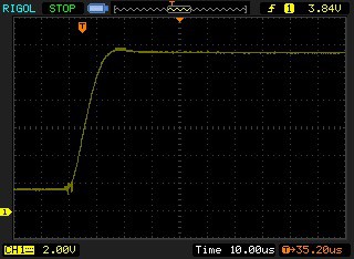
This was a HUGE improvement from the first pass:
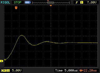
It appears that the input transient problem is solved. The only downside is the additional power dissipation from the 75mΩ input resistor.
All of the other parameters that I measured were consistent with first pass results, as expected. There won't be a third pass. I still need to evaluate the circuit using a 6A switcher IC, but that is pretty low priority.
Discussions
Become a Hackaday.io Member
Create an account to leave a comment. Already have an account? Log In.