 Bud Bennett
The circuit approach has already had several passes before being ripped from the RC Battery Backup project. The biggest change is that the power state memory must be held for 10 seconds if the input power source is disconnected or glitched for any reason. This required much larger capacitance on the VDD line and the removal of any large currents -- like the LED current -- from VDD.
My first attempt, which is already being fabbed by OSH Park, did not include the memory hold function:
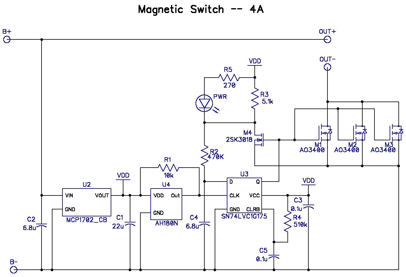
U2 is a 3.3V LDO. U4 is the magnetic field detector. U3 is a D-type flip-flop with CLR that toggles the load switch each time a magnet is brought near the circuit. Note that R2 and C4 have a time constant of several seconds to prevent the CLK pin of the flop from glitching the output at high rates as the magnet is applied and removed. The user has about 2 seconds to apply and remove the magnet to accomplish the switch activation. The memory hold feature can't work with this circuit because the LED current is drawn from VDD and the LDO input is not isolated from the load.
Circuit with memory hold feature:
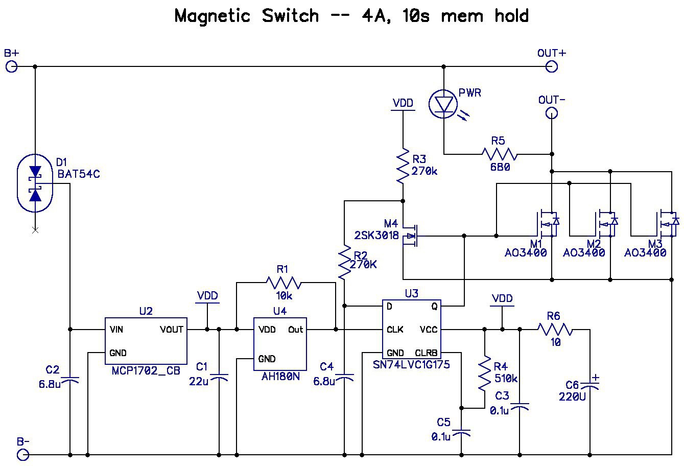
The LDO has a PCH FET pass transistor connected from VIN to VOUT. If the B+ line transitions to a low voltage the VDD line will be dragged down as well. D1 prevents the input from dragging VDD low. D1 also drops about 0.25V, which will impact the operation of the circuit at the low end of the voltage range. All of the circuits operating off VDD are specified to function down to at least 2.5V, so hopefully things will still work with B+ = 3V.
The LED is now drawing current from B+. This gets the high current off of the VDD line, but subjects the LED to wide current variation with B+ voltage. It also stresses R5 with power dissipation near its upper limit. Fortunately, the LED is still pretty bright even with low current (depending upon the LED color). When the first PCB prototypes arrive I will experiment with LED colors and current drain to hopefully find a combination that works. If not, then the LED won't operate at low input voltages, or a circuit change will have to be made.
The capacitance on VDD is increased drastically. C1 increased from 1µF to 22µF, and R6 and C6 were added. R6 isolates C6 from the LDO, which is not stable with capacitance above 22µF. Total capacitance on VDD is now around 240µF. Also, R3 was increased to 270kΩ and R2 was decreased from 470kΩ. This change decreased the on-state current drawn by R3 to around 12µA. The downside is that the amount of time that the user has to change the state of the switch is different depending upon whether the circuit is turning on or turning off. Again, a lot of this stuff can be adjusted after playing with the first prototypes. The memory hold time is estimated by adding up all of the currents on VDD when the load is switched on (about 25µA), dividing that by the capacitance on VDD to get the slope -- ∂V/∂t -- and then calculating how long before VDD drops below the minimum operating voltage of U3, which is 1.65V. I figure it will take about 17 seconds.
Lastly, the single big NCH FET at the output was replaced by 3 NCH FETs in SOT23 packages that I already had in my inventory. This saved me from ordering more stuff from Digikey, and is a bit less money since the AO3400 FET cost me only $0.026/each vs. $0.64 for the big PowerPak FET.
PCB size is expected to be around 10mm x 18mm, which costs about $0.50/each from OSH Park.
Off-State Current Estimate:
U2 = 2µA
U4 = 8µA
U3 = ?? (10uA max over temperature -55°C to +125°C)
Total ~ 10µA @25°C
Cost Estimate:
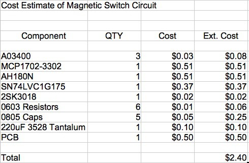
Pretty Cheap!
Discussions
Become a Hackaday.io Member
Create an account to leave a comment. Already have an account? Log In.