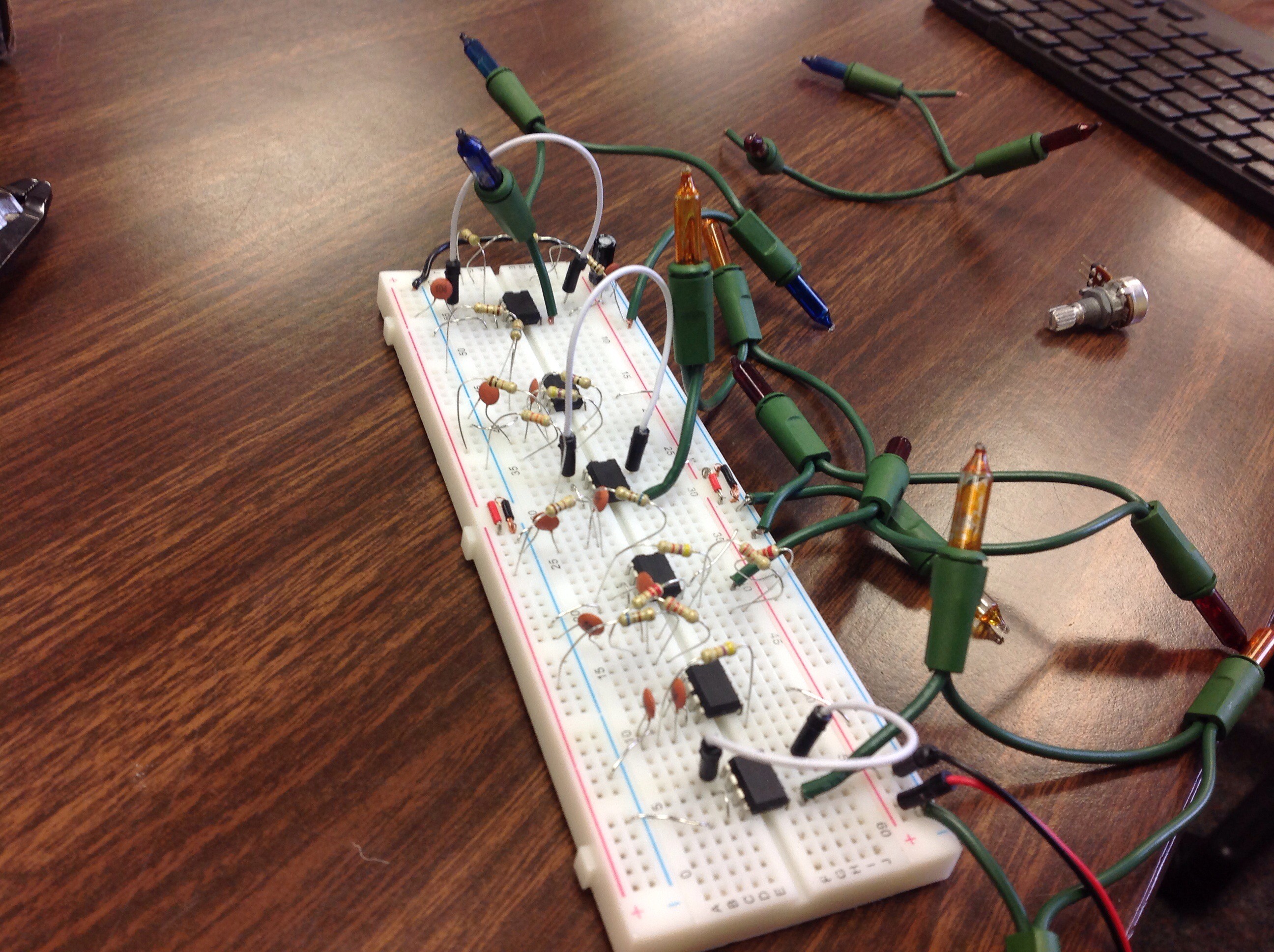
This project aims to help me understand RC frequency filters and the basics of op-amps (and their derivative, LM386 amplifiers). The circuitry forms two main "stages" in which the audio is processed to make a Christmas light display.
Though this is a school project and is being documented in-house, I'm also documenting it here as a means to show the details that hackers and makers might find interesting (while instructors might be more concerned in the physics behind the project). I'm also hoping I might get some feedback to catch mistakes before they happen (though they make for good writeups and learning experiences all the same).
Stage 1: Filtering
This uses the aforementioned RC filters to strip the audio signal into 6 frequencies:
- 0-32 Hz
- 32-256
- 256-512 Hz
- 512-2048 Hz
- 2048-8192 Hz
- >8192 Hz.
Band-pass filters are formed by combining low and high pass filters. Without taking load resistance into account, the equation for a filter's blocking frequency is
However, LM386 amplifiers have a 50 kΩ resistance, so this must be taken into account when calculating resistor values. I'm using 100 nF capacitors for all the filters as that's what I have on hand (I've got a resistor kit for getting odd resistor values).
Stage 2: Amplification
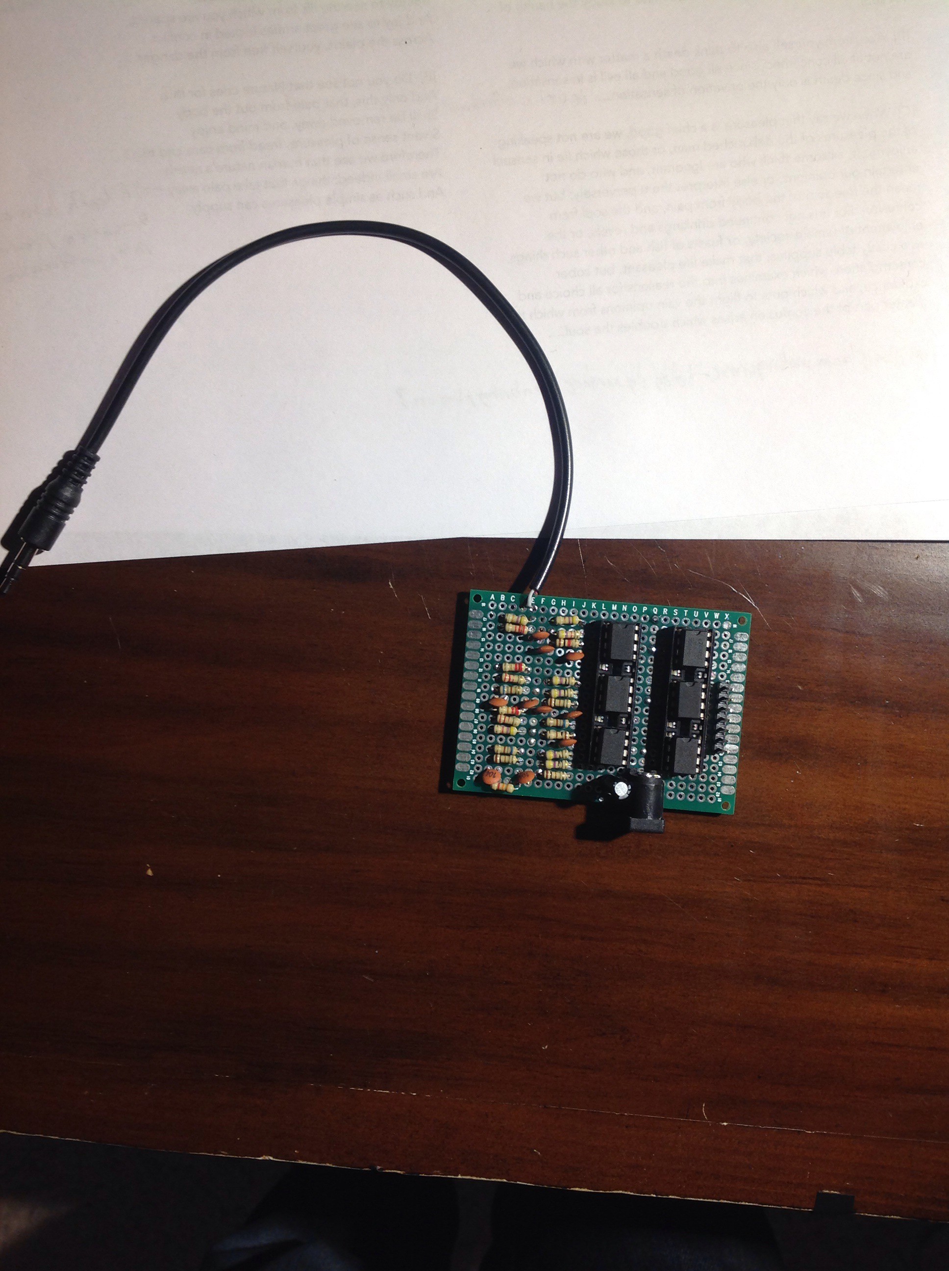
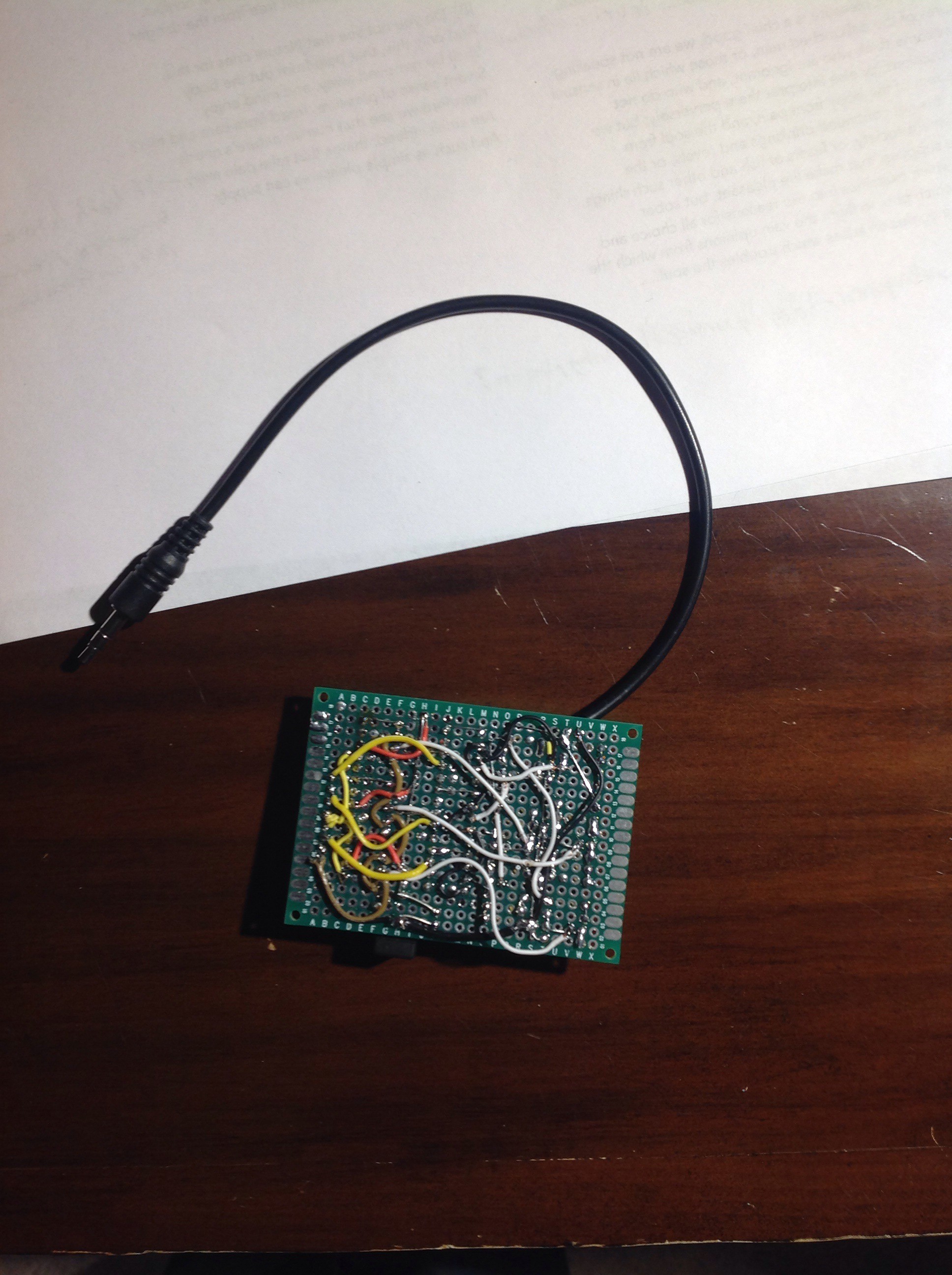
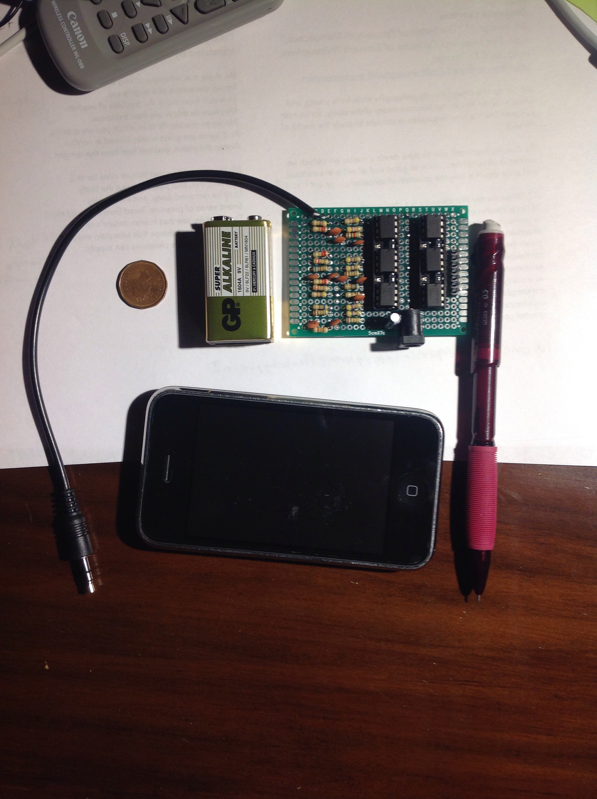
This is nothing fancy, just a LM386 with the default 20 gain, a small RC filter on the end (taken from the TI datasheet-I'm still trying to figure out what that does), and a DC blocking capacitor. Multiply that by six frequency bands, and you get a lot of repetitive soldering. I'm going to power them off of a 12v DC input, so I should get a 6v AC output to drive the Christmas lights (which are around 2v AC each). If there's a small voltage drop, nothing bad happens-the lights just get dimmer. It's too bad I had to order these off Amazon-they come in 5 packs and I needed 6. Oh well, at least I have extras in case one blows up.
 CompuCat
 Rudraksha Vegad
 Sproket
 John Wetzel