 John Taylor
I received the phase current sensing PCB from OSHPark on Monday. I finally got around to assembling it today. Here are some pics.
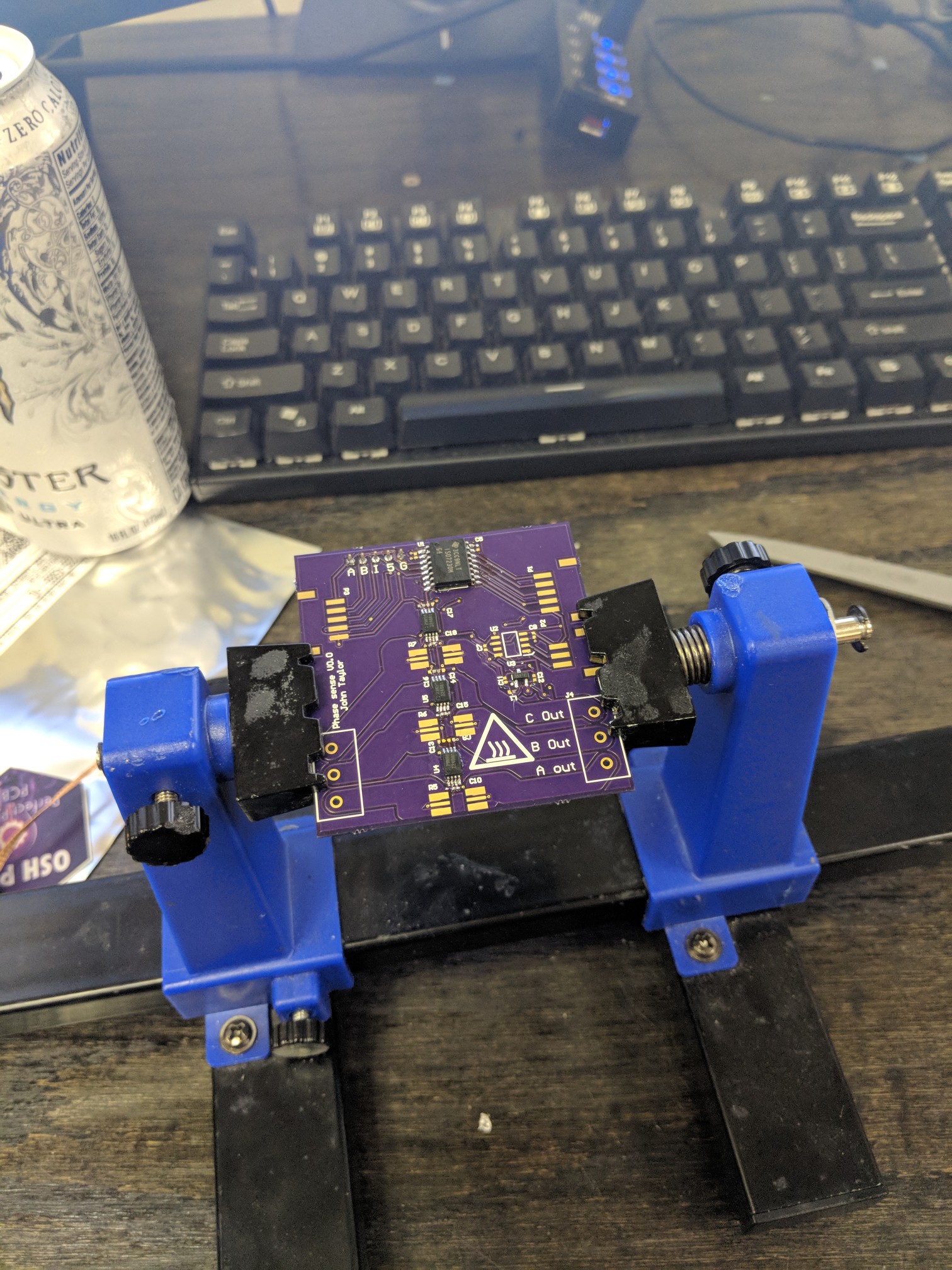
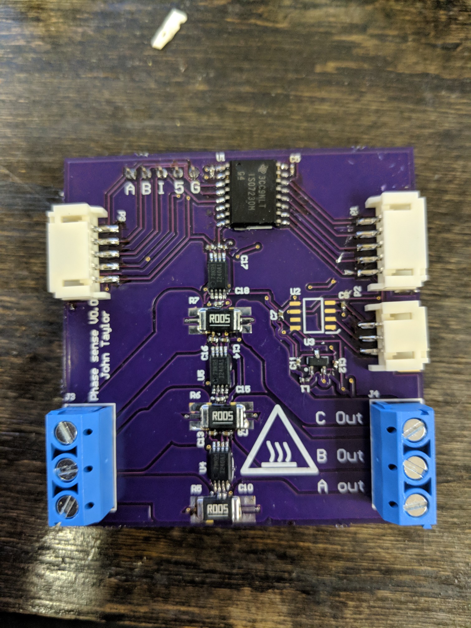
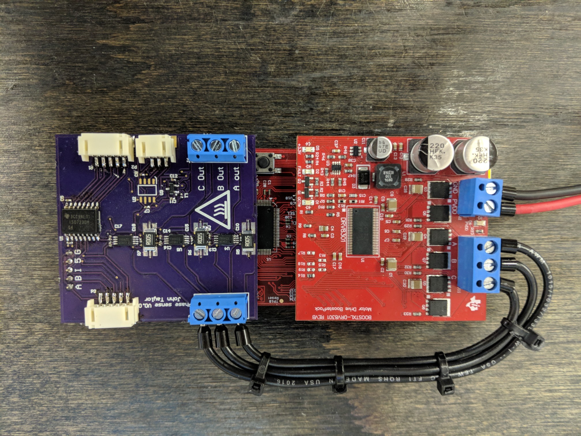
If you look closely, you will notice that U2, one of the isolators, is missing. Unfortunately I forgot to order this part from digikey and I'll have to wait for it to come in. There were a few problems with the board. I used really tiny 0402 resistors and capacitors and from an assembly perspective this made things tedious. I also forgot to put a package outline and a pin-1 callout on the current sense amps so I had to reference the Altium file to figure out which way they needed to go on the board.
Test Plan
- Make sure no power nets are shorted to ground (done)
- power board on (done)
- Check Vref (done)
- Apply i known current through the channels and make sure it shows up on the output of the op amp (done)
- Check all of the digital signals to make sure they are working (done)
I probably wont get to this until late next week because I'm going to be out of town.
Discussions
Become a Hackaday.io Member
Create an account to leave a comment. Already have an account? Log In.