Close
0%
0%

Flicker Measurement Sensor w/ Auto Shutter

The goal of this project is to accurately measure and characterize the 120hz flicker from a variety of light sources.

Similar projects worth following
This project was started based on a need to measure the changes in light that your eyes are unable to detect. With the help of an oscilloscope, this sensor is able to easily show how the light emitter is operating in real-time. My main use for this sensor is to calculate flicker index and percent flicker. It could also be used to measure PWM signals as well as digital communications transmitted through visible light.

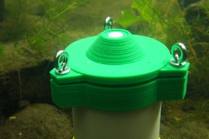
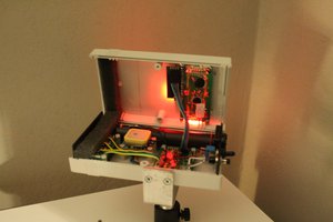
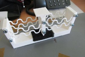
A TSL257T light sensor is used in conjunction with an oscilloscope to capture 120hz flicker in real-time. The sensor consists of a light to voltage converter with a built in op-amp for signal amplification. The device is powered from a 5VDC source and outputs an analog signal from ~0-5VDC. Zero voltage represents no light and 5V an arbitrarily high value. Because the sensor has a fixed amplification, it is easily saturated with low light levels. This makes it useless for measuring an emitting with any significant light output. A automatic linear shutter of sorts was used to restrict the light to the sensor so the peak output stayed around 4.5V. I designed a simple triangle based slider in Sketchup to test my theory. I was able to 3D print it and verify it was good enough. After struggling to add a servo mount in Sketchup, I used this as an opportunity to learn Fusion360. It made it easier to make changes as I went and eventually produced a successful design. I ended up with a simple dual horn linear motion. To quickly get it working, I wrote a simple Arduino sketch to do a peak detect and adjust the servo accordingly.

  • 1 × TSL257-TCT-ND high-sensitivity low-noise light-to-voltage optical converter that combines a photodiode and a transimpedance amplifier on a single monolithic CMOS integrated circuit
  • 1 × 10K 0603 Resistor
  • 1 × LS-0006 Plastic Gear Analog Servo
  • 1 × Slider 3D printed slider
  • 1 × Oscilloscope MDO3000 - Any will work

View all 6 components

  • Scope Captures Resistor vs. CCR

    Andrew Sowa03/02/2015 at 04:36 0 comments

    The scope capture is able to show the difference between using a resistor or constant current regulator(CCR). Both are applied a rectified 60hz AC signal. Because of Ohms law, the resistor will only change the amplitude of the current applied to the led. It tracks the input voltage and produces an output that matches the voltage waveform. The CCR is able to provide a constant current over a range of input voltage. This is shown on the right side of the picture. The current regulation creates a flat stable light output when the input voltage is above a certain threshold. It cannot correct for low voltages in the signal since it does not contain any energy storage devices. Though better than a resistor, there is still significant flicker at 120hz.

View project log

Enjoy this project?

Share

Discussions

Similar Projects

Does this project spark your interest?

Become a member to follow this project and never miss any updates