 MasterOfNull
Moved the bearings into the mirror arm.
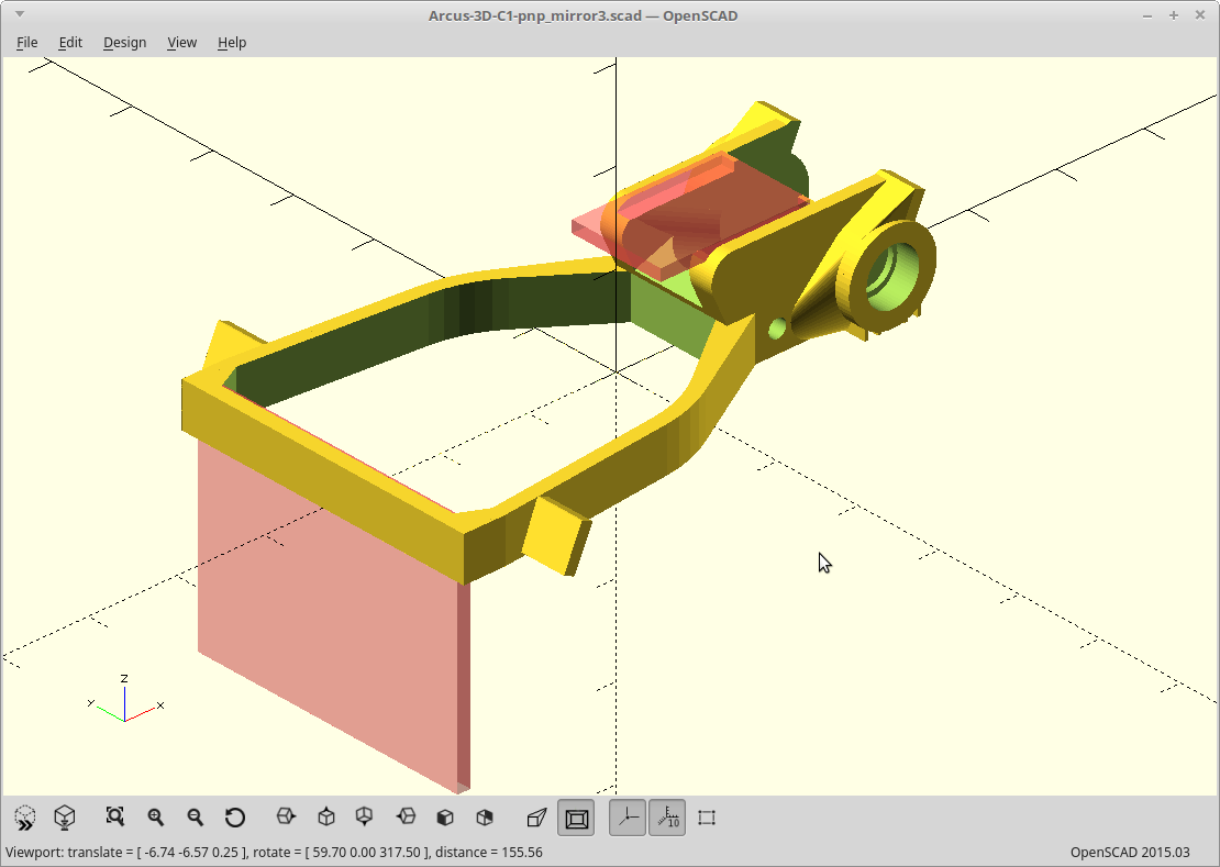
Camera got moved up a bit and the optics adjusted, so if I decide to use a single solid shaft now for the Pi camera version, I could.
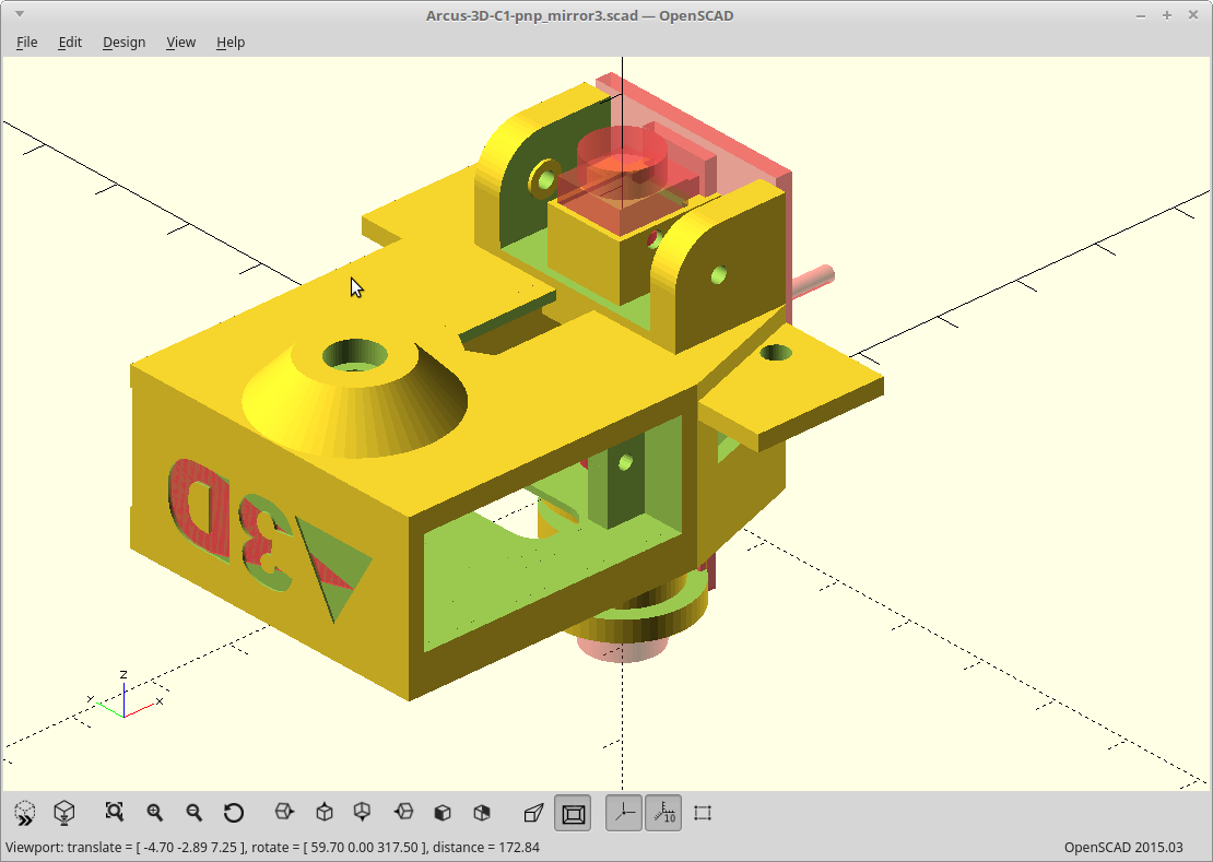
I also decided to go back to a non-adjustable mirror arm stop. I didn't like the idea of snaking a screwdriver along the camera PCB to adjust it. The stop is now printed as a vertical perimeter though so printable accuracy should be really good.
The most critical component positioning is that of the first mirror, so it gets a flat, top surface. Actually, all the optical components mount to either completely vertical or horizontal surfaces for the same reason.
Discussions
Become a Hackaday.io Member
Create an account to leave a comment. Already have an account? Log In.