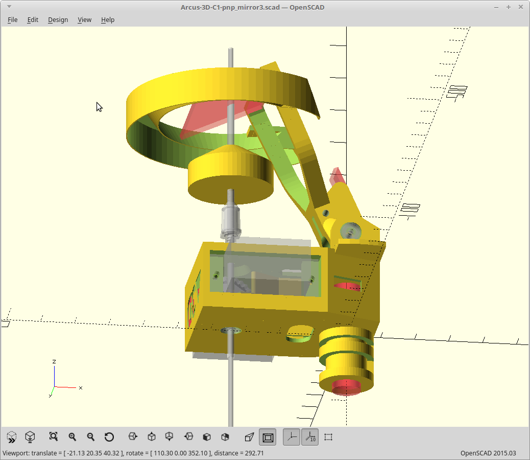
You are supposed to light the bottom vision parts from the side, at between a 45 and 60 degree angle. This is usually accomplished with four LED strips in an angled box, soldered together, etc... Seemed complicated for putting on the arm.
So to keep things simpler, I decided to just use the strip light as a single part, on edge, wrapped into in a cylinder.
Of course I have to leave a gap for the arm to swing over nozzle/parts, and for it to lay flat so it clears already placed parts. Then the remaining inside circumference also has to be a multiple of 50mm as that is where you can cut the strips.. The simplest way was to actually write it out as an equation and solve it.
It ended up being a rather complicated shape, but used less code to do it than most..
Here is what that looks like, for three 50mm light sections.

The LED strip will go inside the outer cylinder. I added the sloped inner ring to reduce glare. It shields the main mirror from being directly lit by the LEDs.
The entire light ring is a single wall print except for the attachment point and weighs less than a gram. The LEDs I'm using are pretty strong, so If I left the lights on for too long, it might melt...
Assembled view.

I had to move my 'wings' up a little bit as the light ring didn't clear the servo's otherwise.
Reprinting the mirror arm now.
 MasterOfNull
Discussions
Become a Hackaday.io Member
Create an account to leave a comment. Already have an account? Log In.