I spent some time thinking how to make the building process as easy as possible, after all the motor needs to be printed, colied, assembled, mounted and controlled. The first concept wasn't very user friendly in that sense.
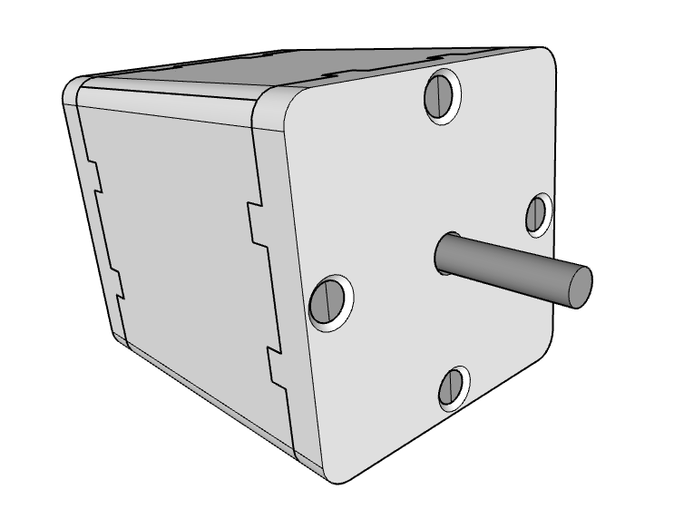
 Fig. 1: New concept. Looks like a standard stepper motor.
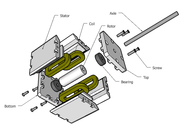
 Fig. 2: Exploded view of all the parts.
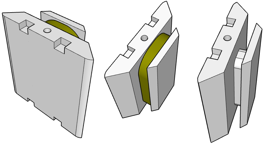
 Fig. 3: Rotor.
This second concept is all about using off-the-shelf parts. It's controlled like a 2-phase stepper motor when the rotor has magnets on it (synchronous) and when coils are put on the rotor it works as an asynchronous motor.
This makes it easier to control, stepper controllers are really cheap these days and I happen to have some at hand so I won't have to build custom electronics.
For the rotor it's probably better to use something sturdier than a printed axle, a metal rod will do. I decided to use the tiny 635 type ball bearings on either side of the rotor as well. The motor can still be made with only printed parts though.
This is still a concept, I haven't printed anything yet because I don't have access to my printer currently.
Discussions
Become a Hackaday.io Member
Create an account to leave a comment. Already have an account? Log In.
Love the new design. Do you have the cad files? I'd like to try and cut them into 2.5D for those of us with a CNC but no printer.
Are you sure? yes | no
Sure, here you go (Google SketchUp file): https://www.dropbox.com/s/abqmtls4qyvz9tp/Square.skp?dl=0
The rotor is just a place holder for now. I'm thinking that the first concept was too ambitious (with the 100% custom motor design) to be feasible in one shot. I think I'll dial it down with more restrictions, I'm thinking about using the NEMA standard sizes and only allow few custom parameters for the first version.
Are you sure? yes | no