 Emach00
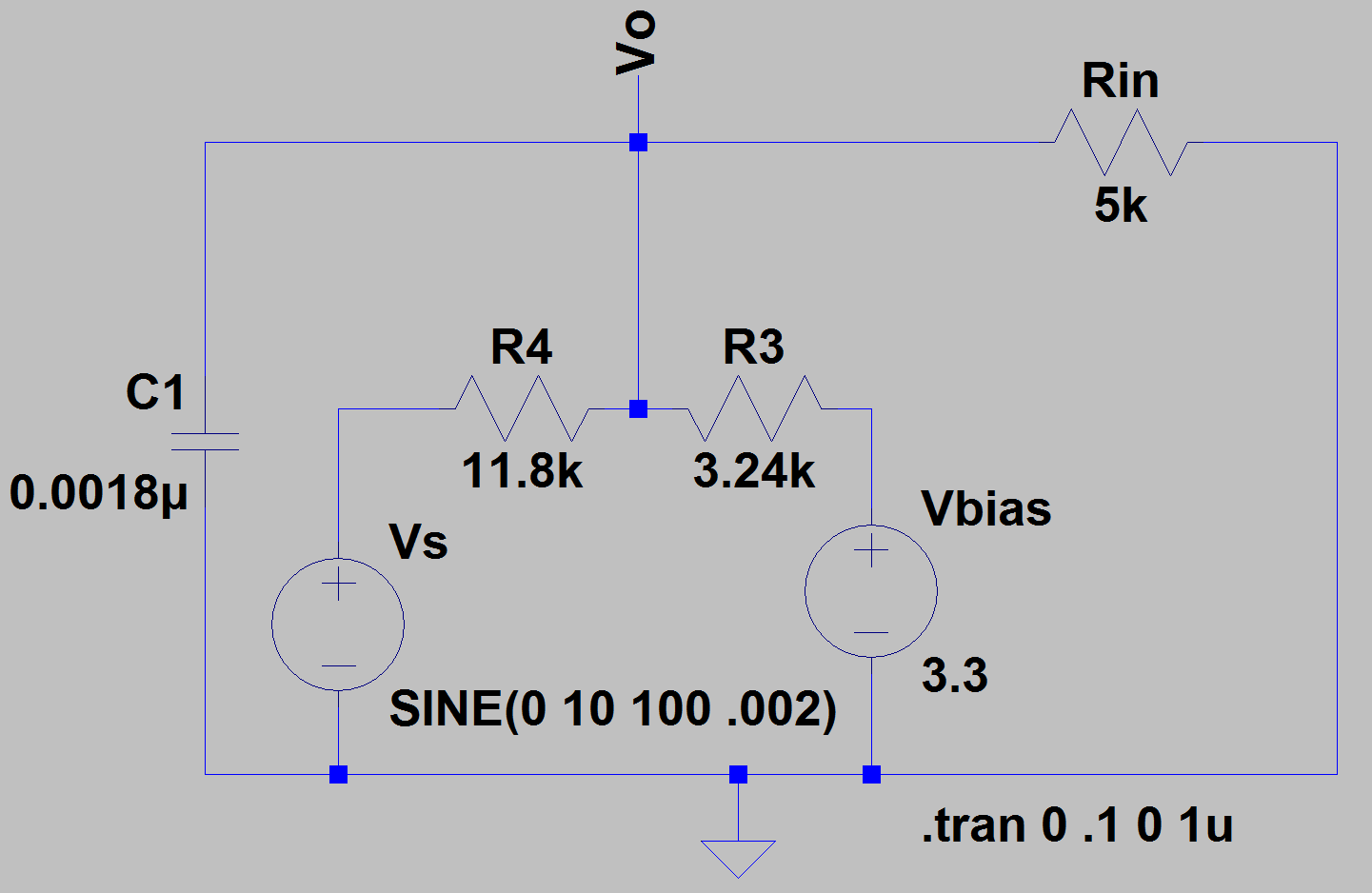
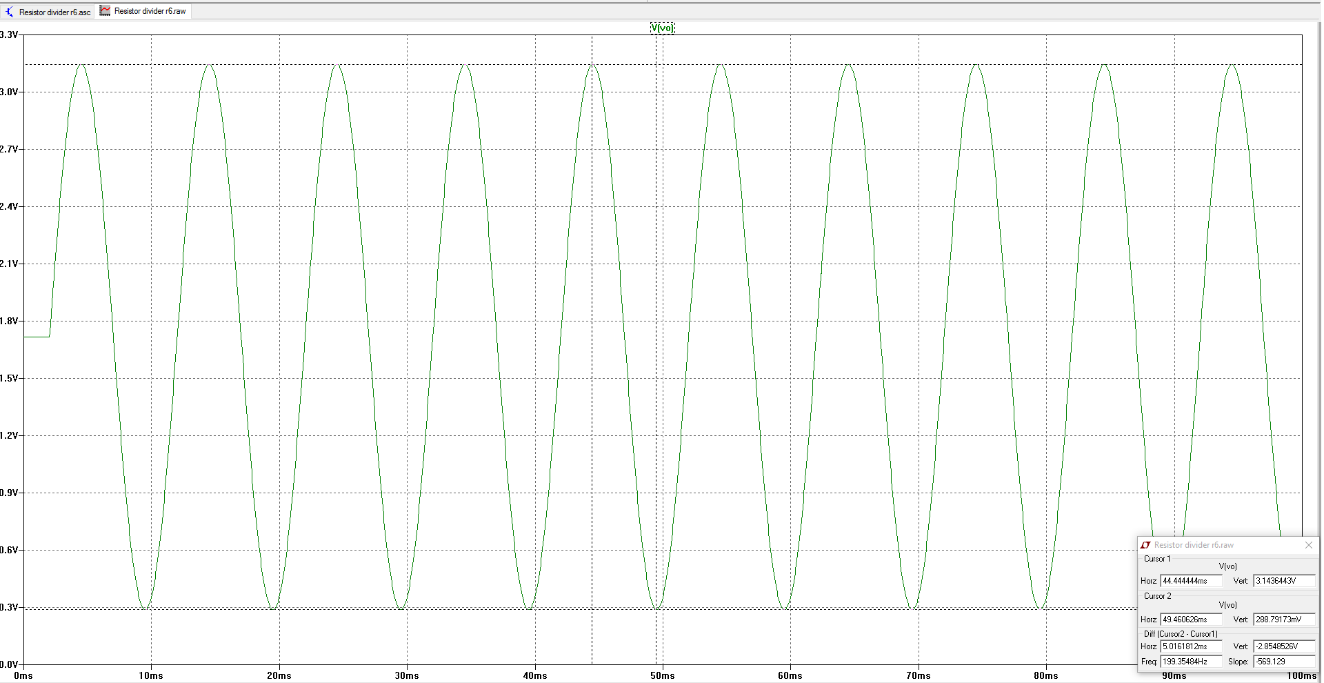
Following advice, I used the 3.3V as my bias voltage. Can't quite seem to get it down to 0V but this would work too with minimal additional components.
A project log for +/- 10V to 0-3.3V Translator
Differential Op-Amp Circuit to translate +/-10V DAC signals from test equipment to 0-3.3V for Teensy 3.6 Board
Following advice, I used the 3.3V as my bias voltage. Can't quite seem to get it down to 0V but this would work too with minimal additional components.
Discussions
Become a Hackaday.io Member
Create an account to leave a comment. Already have an account? Log In.
Rin is there to represent the input series impedance of the ADC. https://www.pjrc.com/teensy/K66P144M180SF5V2.pdf
page 45. Thanks for the suggestion, will definitely simulate it.
Are you sure? yes | no
Rin = 5K loads the output of the voltage divider, so the amplitude will be a bit lower. It also changes the DC bias point slightly. In my circuit, the ADC input has very high DC input impedance. C1 acts as low pass filter, lower AC impedance and provides charges to the ADC during sampling, so you don't need to have Rin connected.
If you change R4 to 10K (while keeping Rin), the output switch of your circuit will be centered at 1.673V and swing from 33mV to 3.314V While not perfect, it is probably close enough.
Are you sure? yes | no