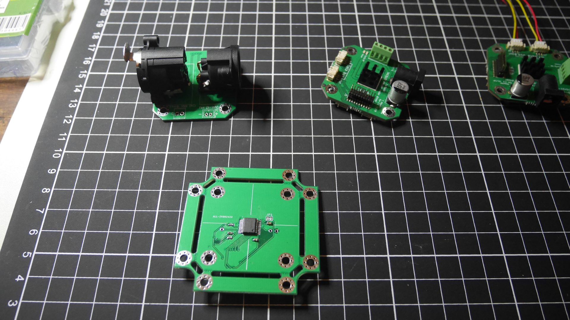
I finally took some time to solder the magnetic encoder and XLR PCBs.
Here they are :

The encoder boards has a AMS AS5132 chip, which should be capable of a 1° resolution.
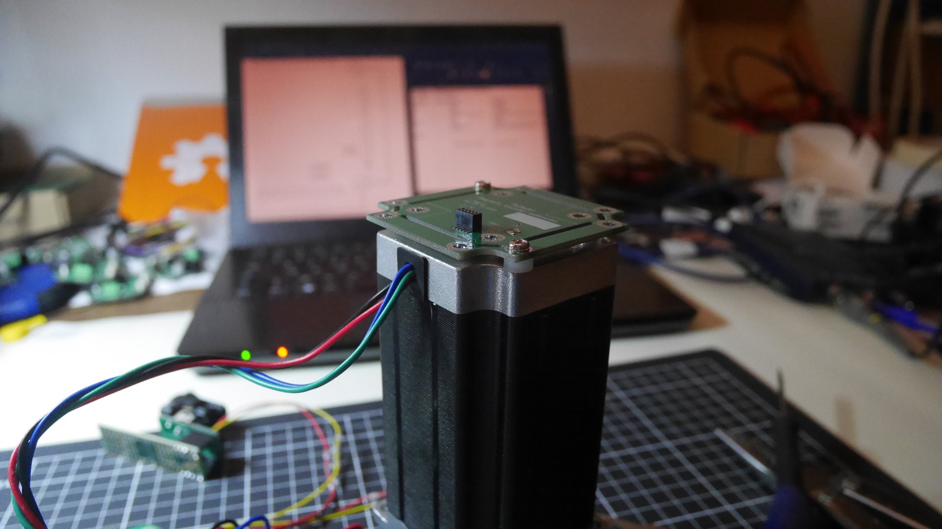
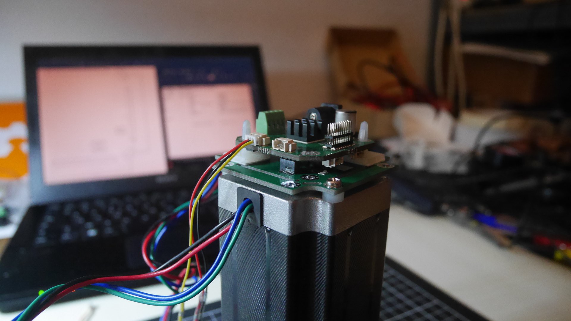
It has a NEMA23 form factor and can double as a mounting support for the TMC5130 board.


I haven't had the time to test it with the TMC5130 but the encoder IC seems to work :
The yellow LED is connected to the PWM output of the encoder IC, that encodes the angular position into the duty cycle. On each turn of the motor a ramp followed by a step is clearly visible, which means that the encoder works !
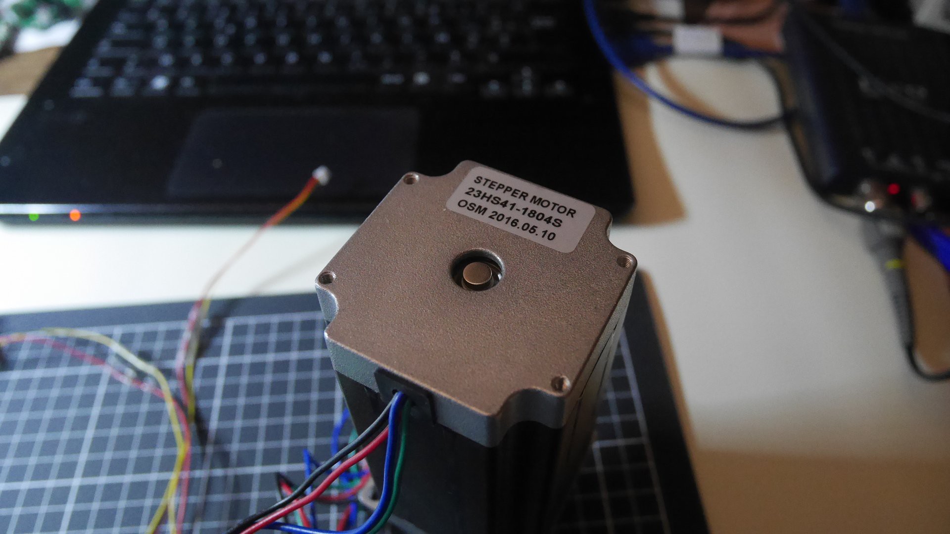
I will still have to experiment with the precision, but I think that the magnet placement is not ideal : too far away from the chip (the datasheet suggests a 1~2mm distance, here it is at least at 4mm) and stuck directly on the shaft which weakens further the magnetic field.
 Tom Magnier
Discussions
Become a Hackaday.io Member
Create an account to leave a comment. Already have an account? Log In.