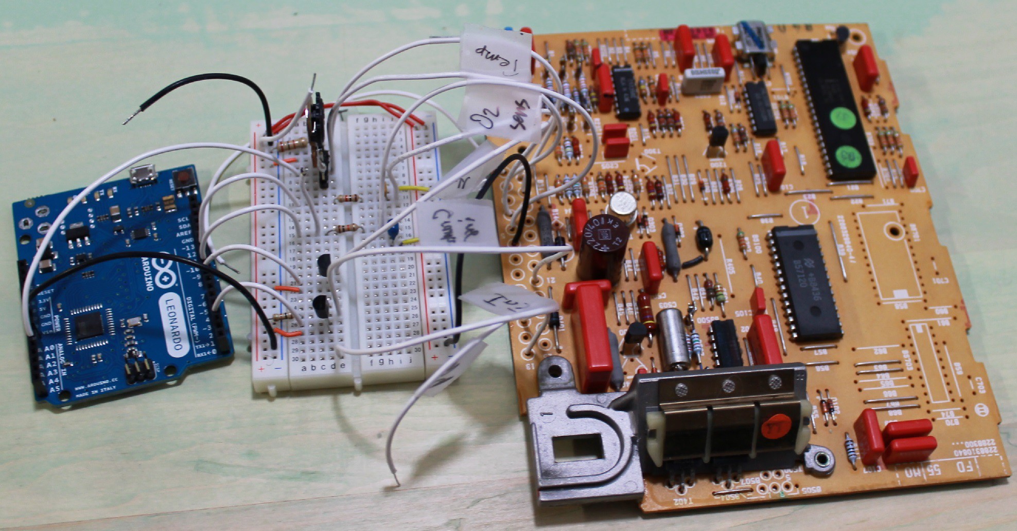
Goals:
- Obtain a fuel map from the original VW ECU as a starting-point for ECUality
- Answer questions about how the original ECU behaved, such as:
- What aspect of the O2 sensor signal does it care about? (threshold crosses/sec? DC voltage?)
- Generally, does the optimization routine change the "shape" of the map, or just apply a global offset?
- How fast does the optimization respond?
Here, I use an Arduino Leonardo to send signals to the original ECU that simulate sensor data from a running engine. With that stimulus going in, I record the pulse-duration of the injector signal coming out.
The breadboard between the Leonardo and the ECU contains:
- a couple RC (low-pass) filters for smoothing PWMs into analog voltages.
- a couple N-mosfets for handling a voltage-shift (0-5V to 0-12V)

 Mike Thielvoldt
Discussions
Become a Hackaday.io Member
Create an account to leave a comment. Already have an account? Log In.
An engine fuel-map:
This was obtained at an O2 input of .5V, which I found to cause the injector duration to remain constant. The air variable represents the 8-bit pwm value that was used to simulate the 0 - 5V signal produced by the air flow sensor. 255 would correspond to 5V. 0 to 0V. Linear in between.
The left column is the air variable,
The top column is the RPM variable.
the block of data in between is us/4 of injector duration. (to get microseconds, multiply these numbers by 4).
RPM: 500 695 965 1341 1863 2589 3589 5000
air: 220 2470 2470 2472 2464 2471 2464 2459 1917
air: 180 2162 2170 2160 2160 2333 2021 1597 1204
air: 140 1900 1898 1918 1896 1632 1236 943 765
air: 100 1789 1750 1618 1228 948 755 616 596
air: 80 1518 1498 1177 941 749 622 588 563
air: 60 1294 1291 944 773 636 637 587 560
air: 40 1164 1160 779 776 678 648 587 561
air: 20 1123 926 786 826 719 631 900 589
Are you sure? yes | no