This project log discusses using the relay board without the ESP32. There's now a board designed specifically for this: https://hackaday.io/project/46280/log/144065-lo-tech-muffsy-stereo-relay-input-selector-without-esp32
One problem with projects like these is that the wiring has a tendency to end up as a heap of spaghetti.
So I've been wondering about how I should do the rotary switch in particular (in a setup without the ESP32 module). This is the simplest setup, and you don't have to write any code at all.
Coinciding with this, wireless coverage isn't that great in my new house. So I bought a Google Wifi bundle, and look what came with it:
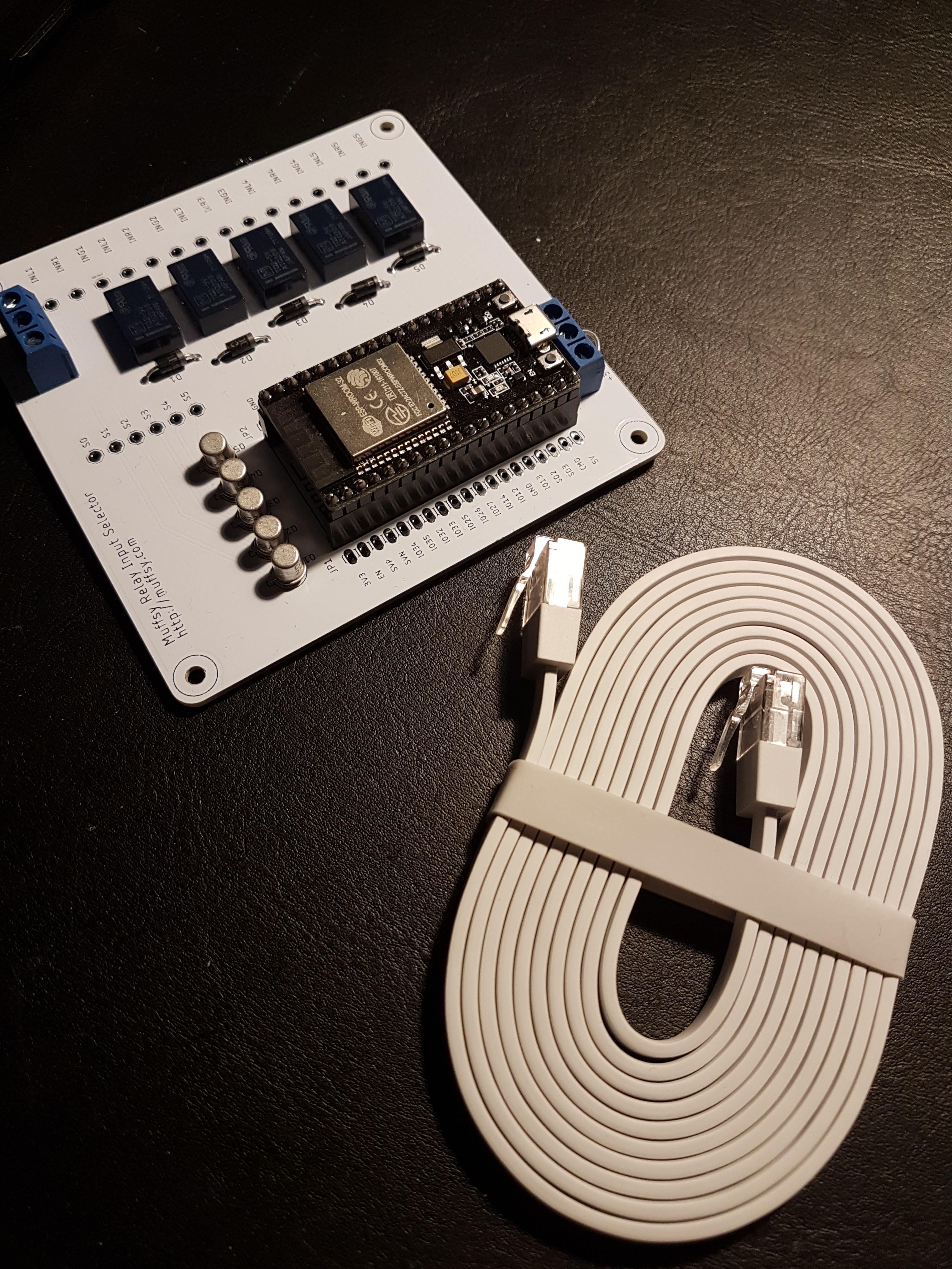
Yup, a very flat network cable. Great timing, hey? Let's get snipping!
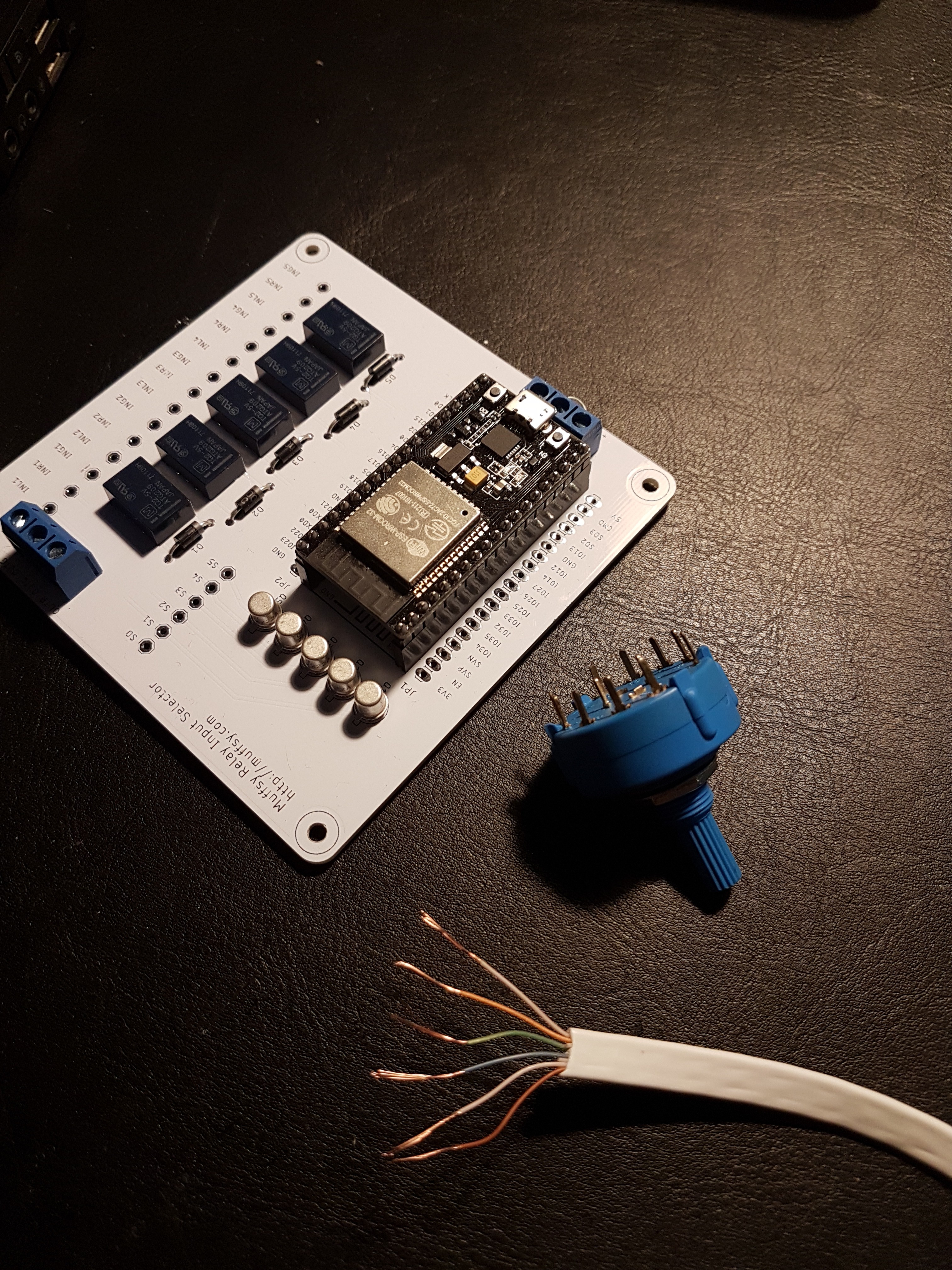
I kept the white leads on each side, and cut the white ones in the middle. The switch is 2P5T, I'll only use one of the poles. Yeah, and the ESP32 module will be removed.
Here's the board without the ESP32 and the transistors, cable fully connected:
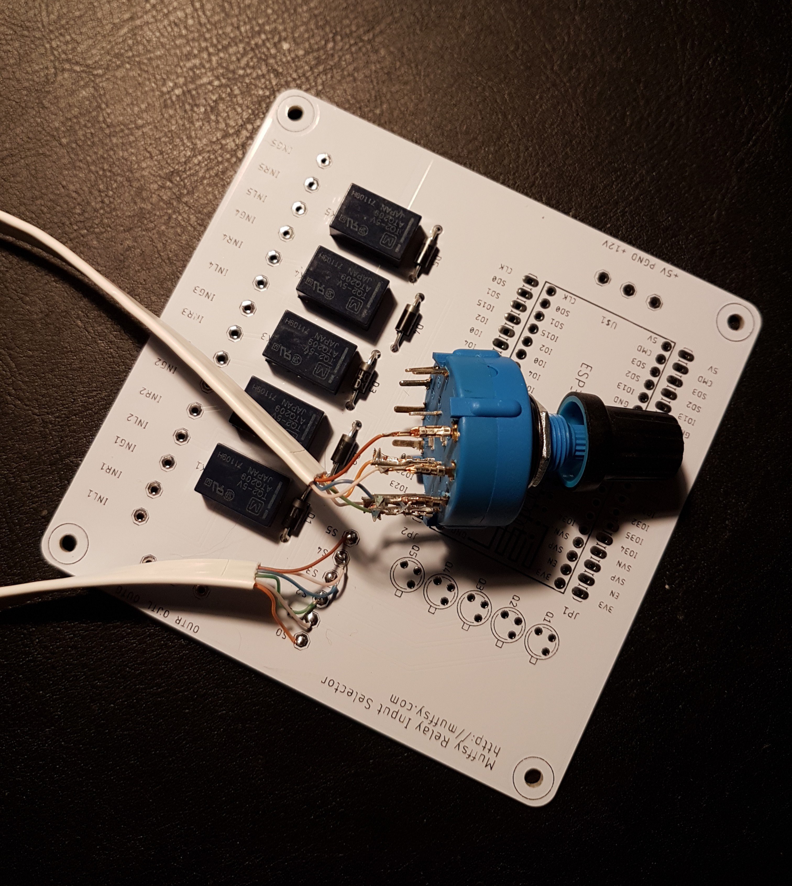
There are crimp connectors on the rotary switch, since it's fairly sensitive to heat (such as from a soldering iron). That's it, apart from connecting power to the relays, connect inputs and output, and cut the flat cable to the correct length.
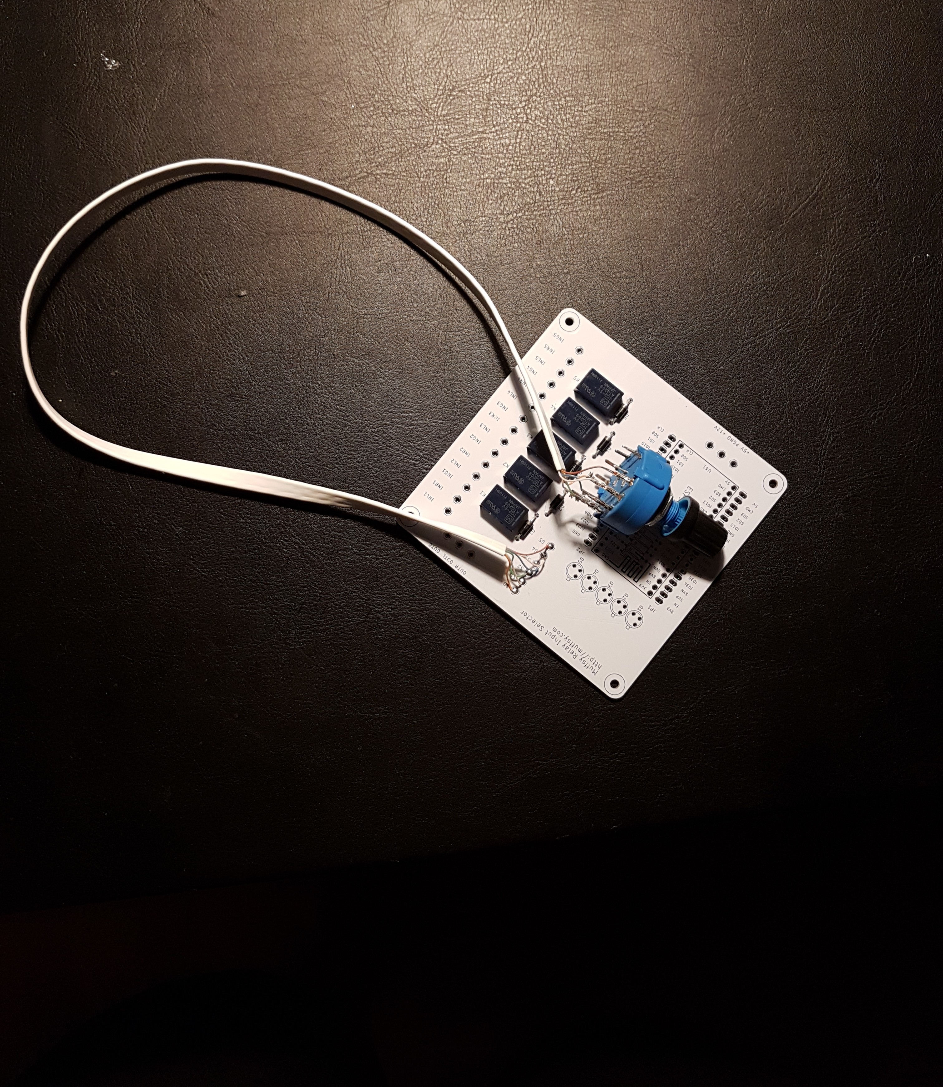
Finally, with power connected. The rotary switch works perfectly, turn it to slowly and it will break one channel before connecting the other one. So no two channels mixed at any time.
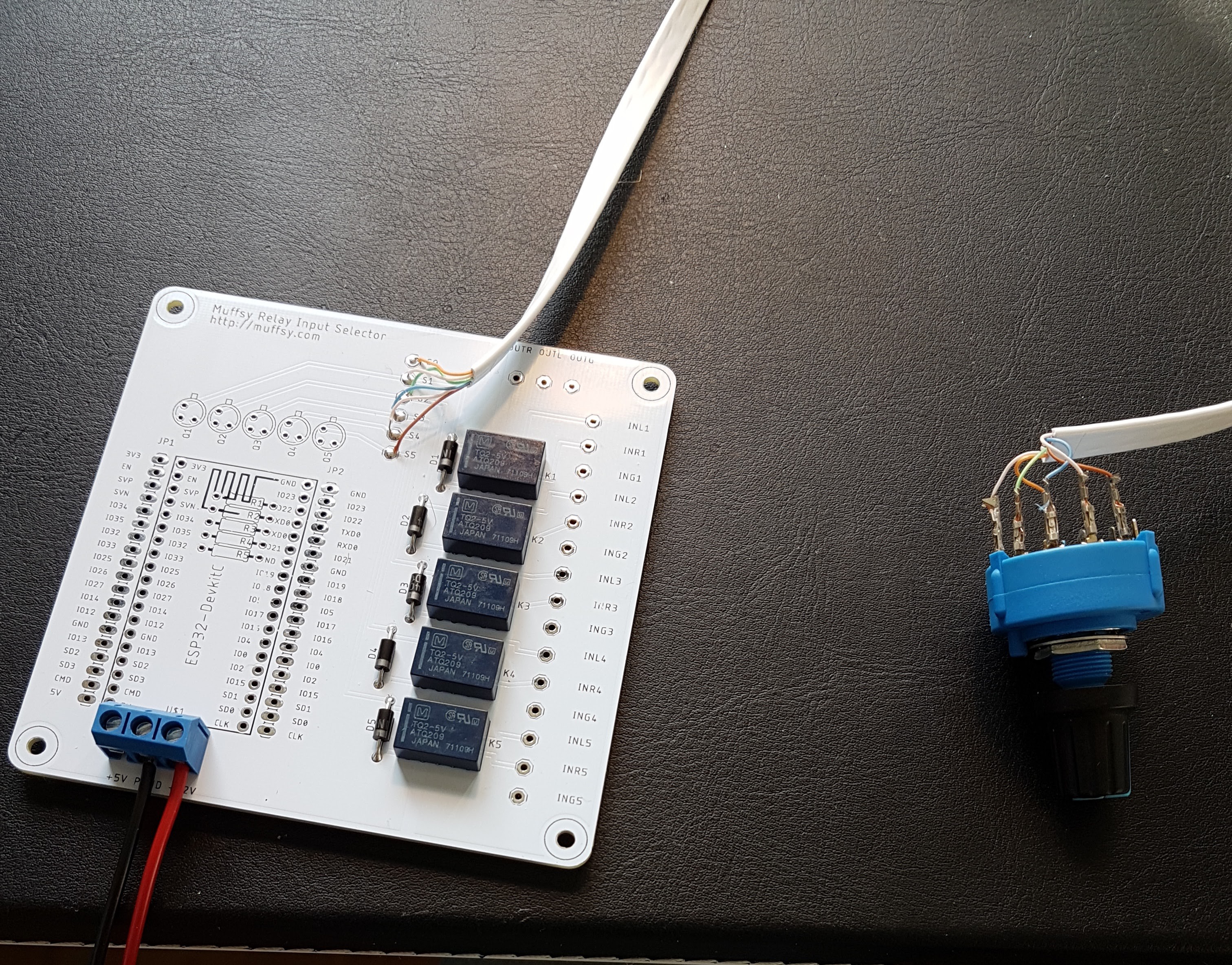
There you have it. A stereo relay input switch that can be controlled by either an ESP32-module or a rotary switch. Fully tested and all.
Discussions
Become a Hackaday.io Member
Create an account to leave a comment. Already have an account? Log In.