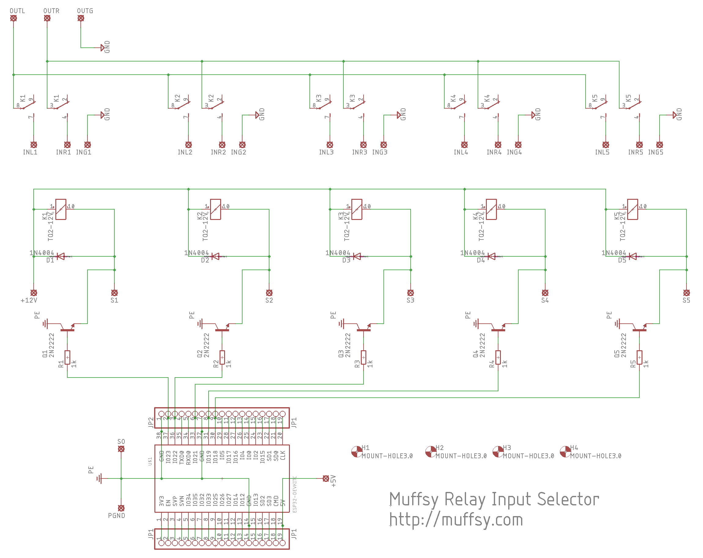
Here are the five relays, all controlled by the ESP32 (or a rotational switch, using S0 to S5, S0 being the center pin).
Five stereo inputs, one stereo output.
The ESP32 switches the relay power to GND using transistors connected to IO23, IO22, IO21, IO19 and IO18.
Power ground and signal ground are separate.

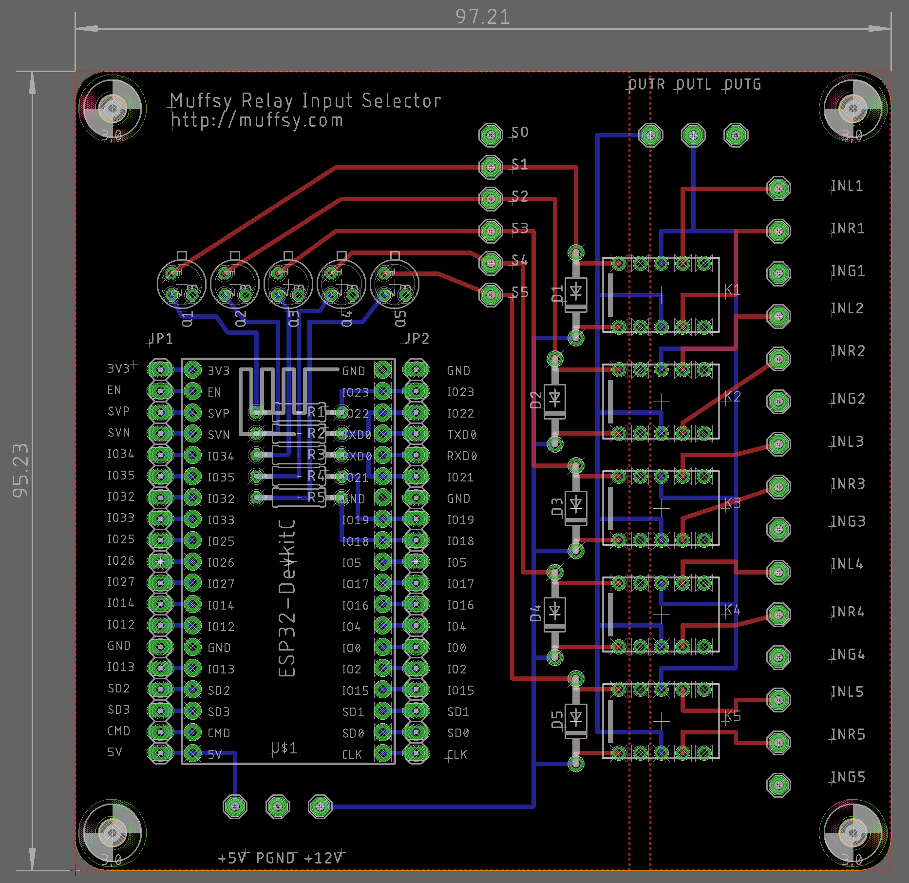
Here's the routed board with dimensions in mm:

Power inputs and signal inputs/output have 5.08 mm pitch (0.2") to accomodate screw terminals.
The solder pads for the rotational switch (S0-25) and ESP32 break-outs have 2.54 mm pitch (0.1").
Discussions
Become a Hackaday.io Member
Create an account to leave a comment. Already have an account? Log In.