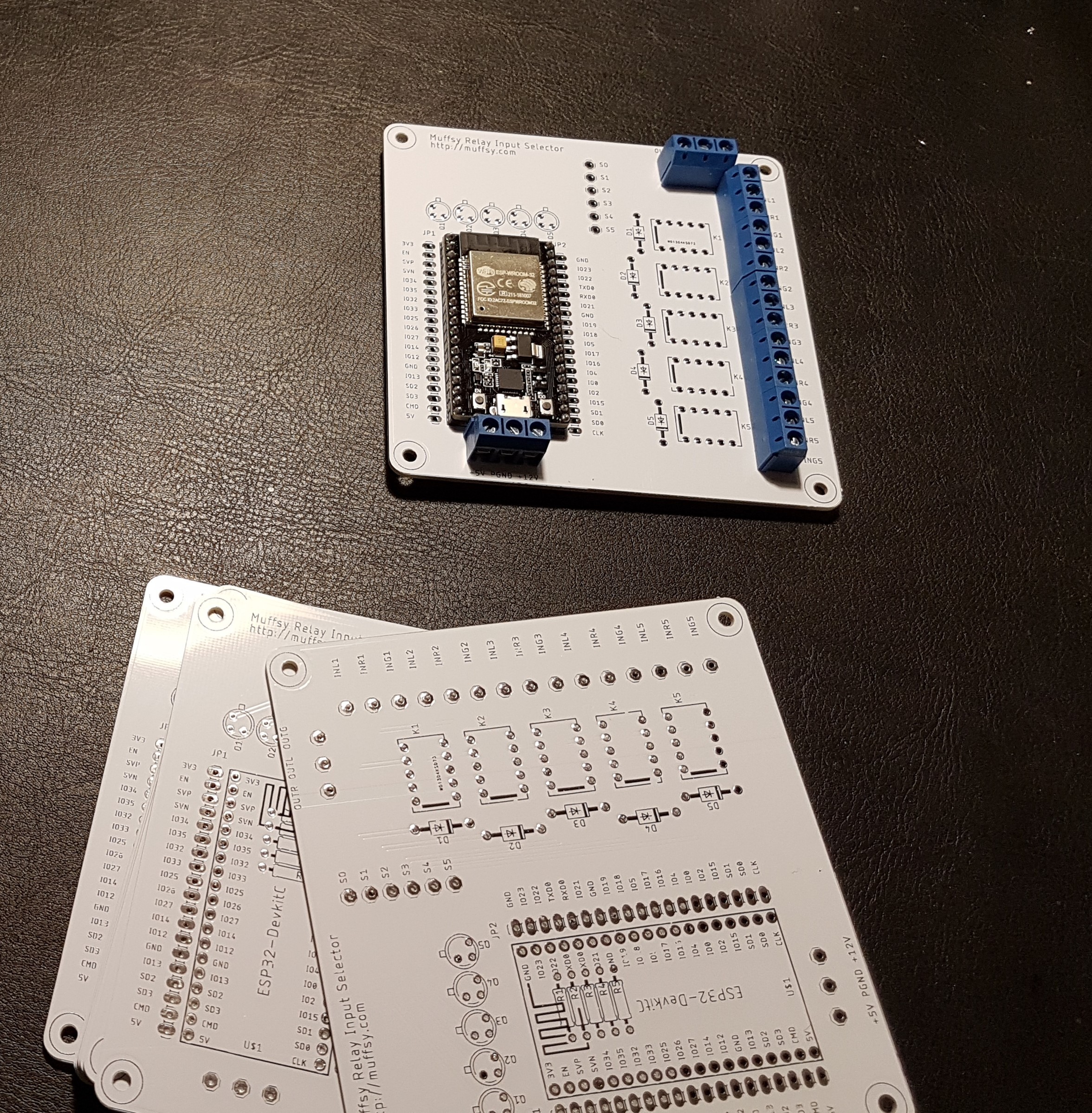
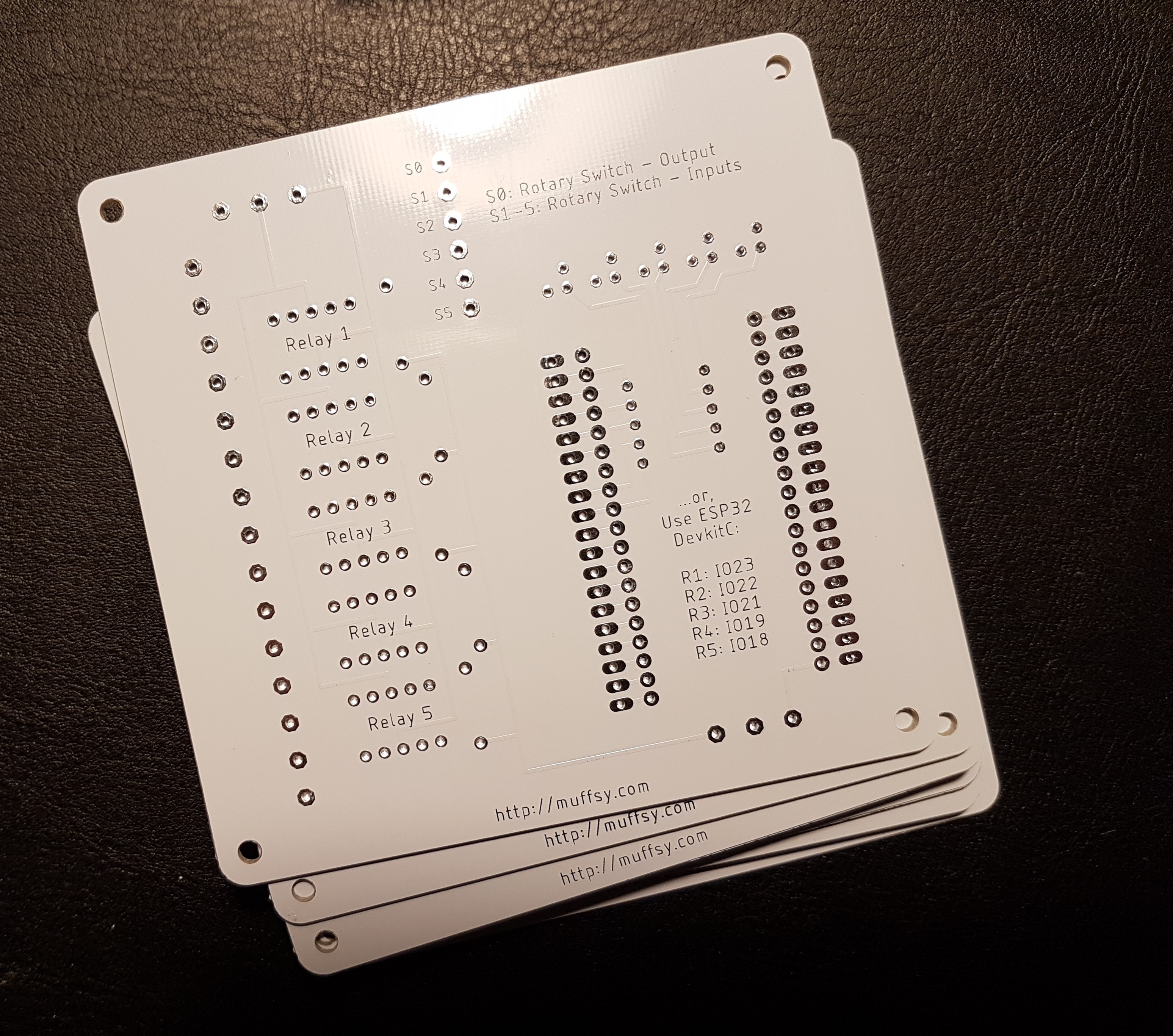
The slow boat parked outside my house today and brought with it some shiny white PCBs.
As you can see from the pictures, it's already built. The board was tested successfully using a short loop turning the relays on sequentially. I was able to verify that each relay turned on and off using the continuity tester on my multimeter.
This first picture shows a test mounting of the ESP32S and the terminal blocks for signal input/output.

A first for me, silk screen on the back:

Stuffing the board was a quick job. Since my pin headers haven't arrived yet (and I am quite excited to see if it works), I soldered the ESP32S to the board.
I need to either skip the terminal block for input power, or be really convinced that my programming is correct before I mount it. The screw terminals will block the USB connector of the ESP when in place. Of course, I am going to build a few more, so I might just consider this the prototype.
Here's the completed board, without any kind of sensors or mechanics for actually switching channels:

Discussions
Become a Hackaday.io Member
Create an account to leave a comment. Already have an account? Log In.