 Muth
MuthStep by step...
I'm quite advanced now with the soldering of the boards. However I'd like to test the multiplexing of them.
First I start to think how mount everything on the screen back :
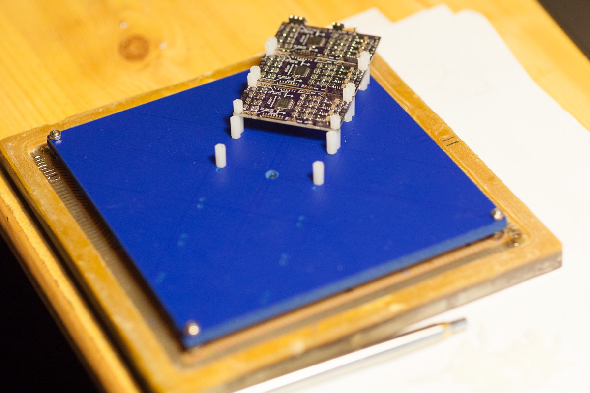
It fits very sharp on the diagonal.
I decided to switch to a smaller micro controller, one of the PIC I already have and used for the LCD big_clock. With it I can easily scan the boards and pins plus enable serial interface. It have plenty enough of RAM as well.
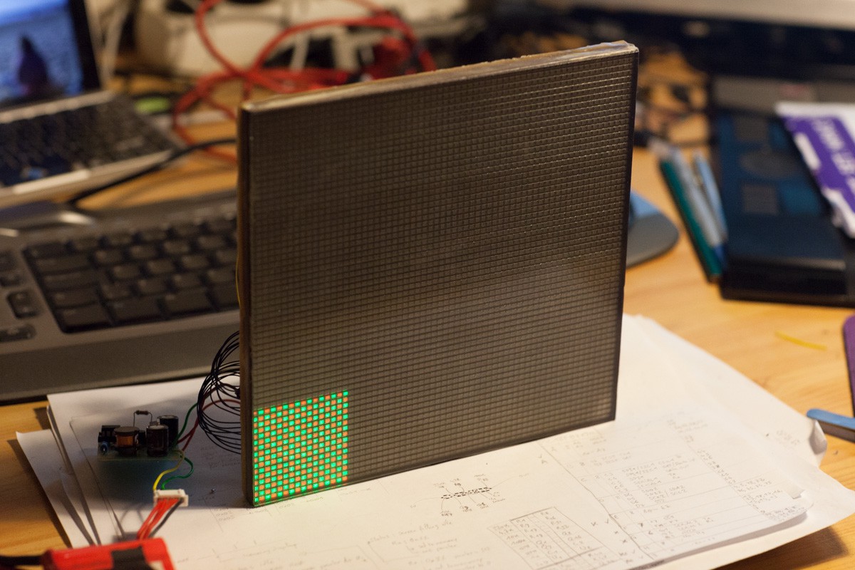
Then I cabled 2 boards for 16x16 pixels drive :

And well, it start to be more and more likely this strategy could work !
Next step: more cabling ;)
Discussions
Become a Hackaday.io Member
Create an account to leave a comment. Already have an account? Log In.