 Muth
MuthFortunately I know a Russian colleague that helped me to understand a bit further the panels datasheet.
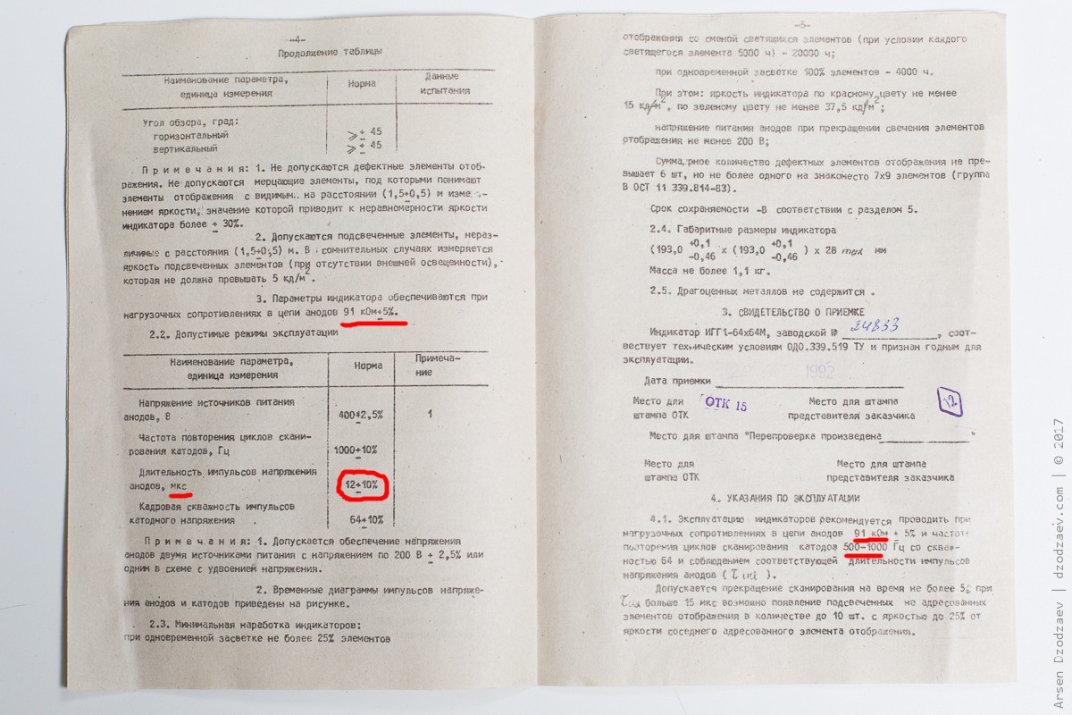
The two important parameters I missed was the anode load, which appear to be 91KΩ, and the pulse length that should be 12µs. Additionally with a frequency of 500 to 1000Hz and a duty cycle of 64.
On google, or even Ebay, you may find these kind of appealing images :
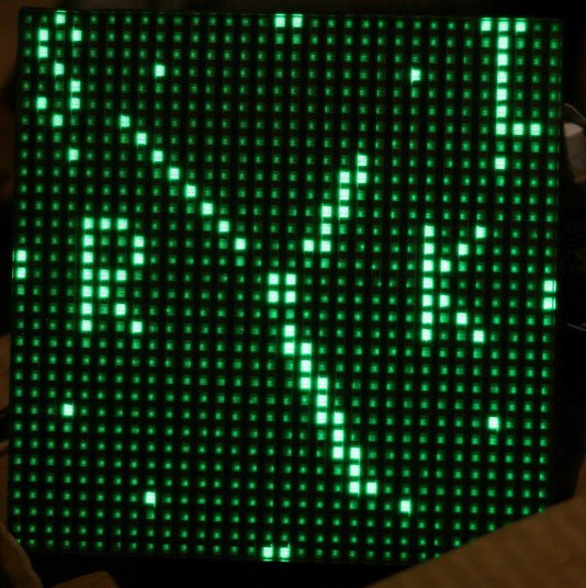
And if you insist gently on google, you will eventually find this Russian forum. Here google translate is your good friend. I suppose it is the origin of this image, http://radiokot.ru/forum/viewtopic.php?p=461563#p461563, done by SLvik :

A bit more roaming here and I found this image:
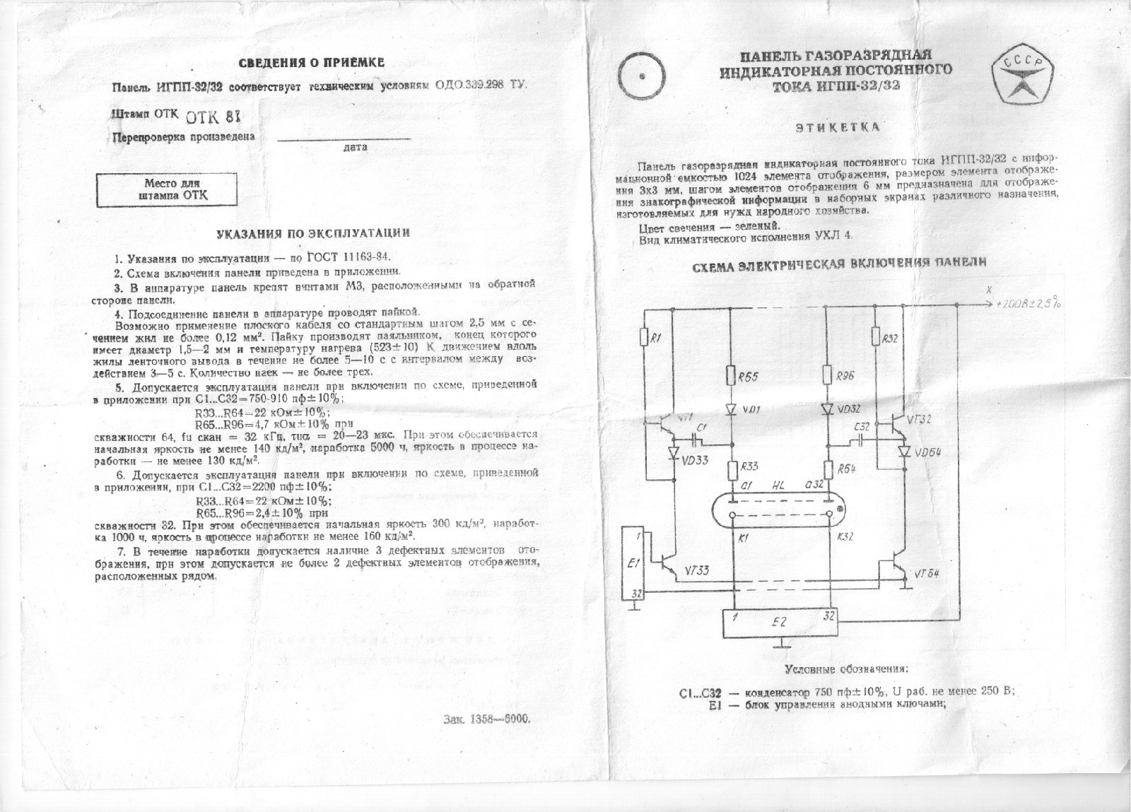
http://www.radiokot.ru/forum/viewtopic.php?p=2547127&sid=804d6efe3e14ad54b9ec8e56b7a81830#p2547127
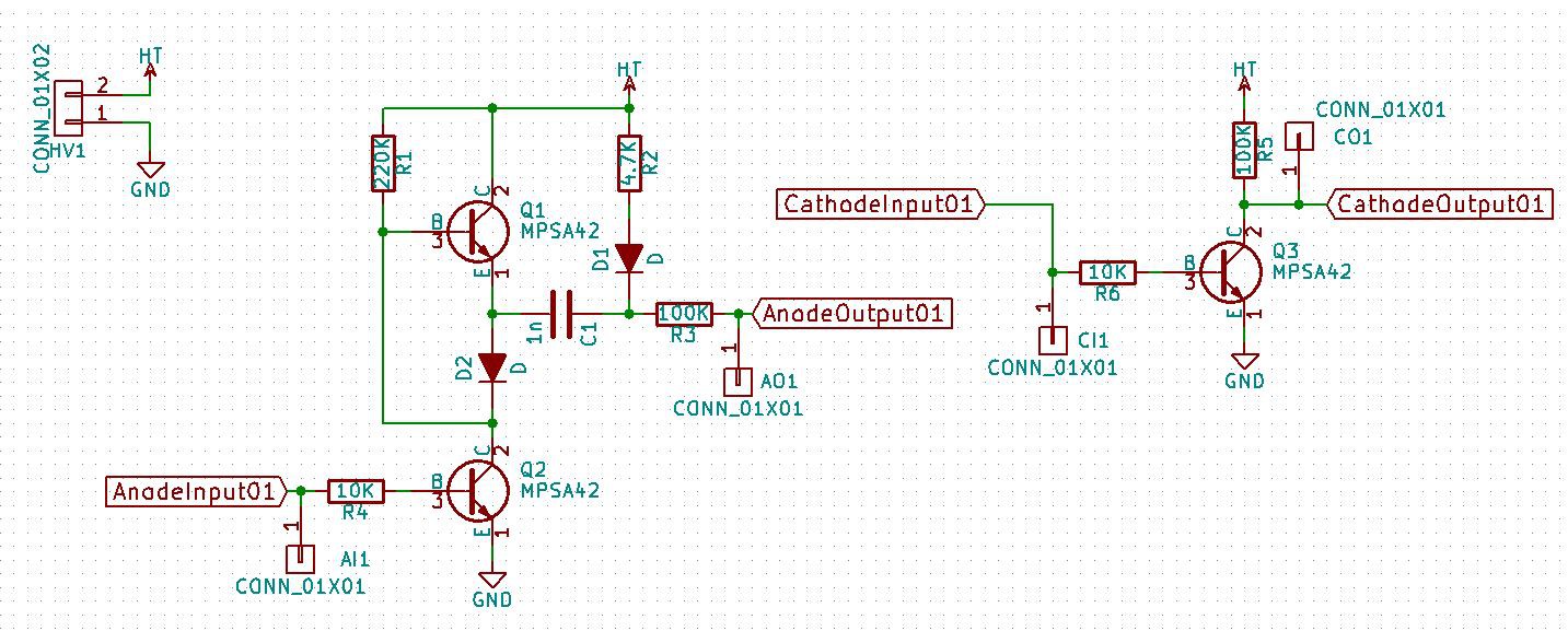
So my wild guess from the youtube video was not so wrong. So lets draw the schematics with better values:
And cable a 4x4 matrix to test everything:
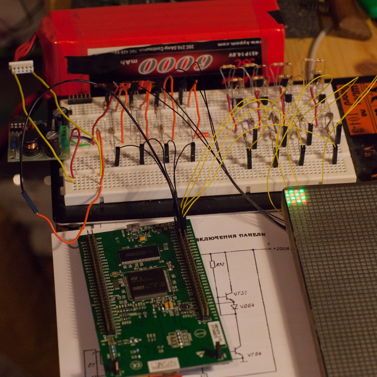
And there were light !

As you can see, I use a quick and dirty program on an overkill STM32 (F429!) with mbed to scan the cathodes and put synchronously some pattern on the anodes:
Discussions
Become a Hackaday.io Member
Create an account to leave a comment. Already have an account? Log In.