 mauswerkz
I ran one test with an arbitrary load setpoint and the speed set to 1400rpm. This was running on only 200v so I was probably right up against field weakening at this point. Below is a quick plot of the results.
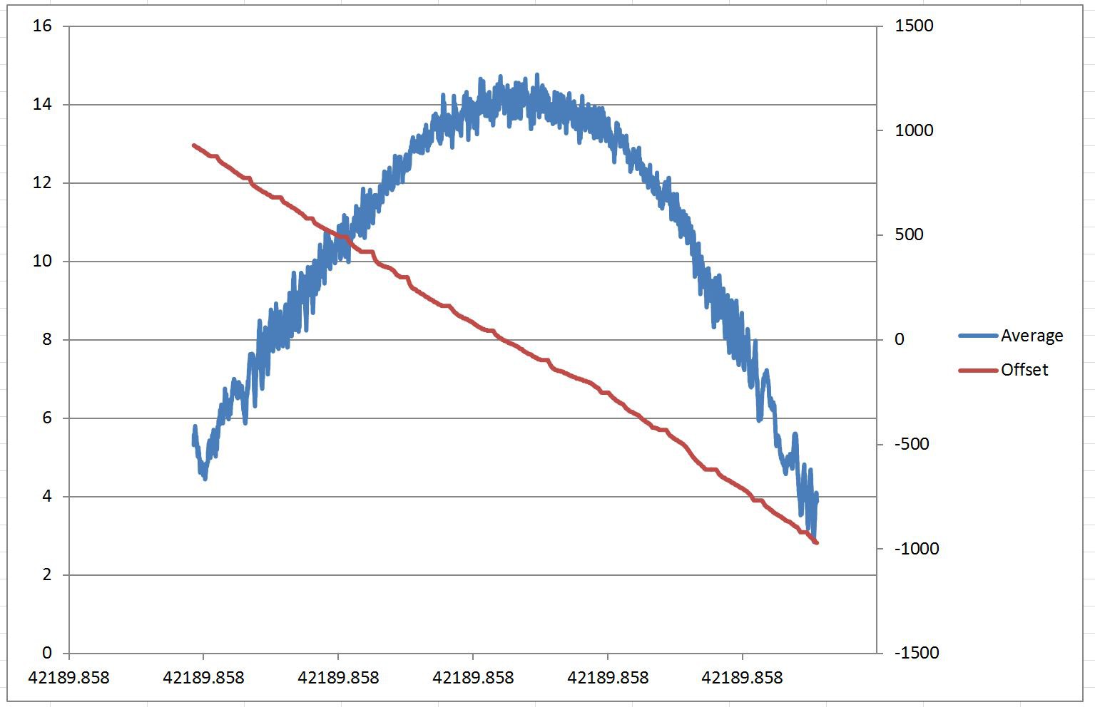
The red line is the offset angle of the opposing (driving) motor.
Instead of using Iq and Id decoupled, Id always has a setpoint of zero and Iq is the only current setpoint used. The offset angle is the value (4095 = 360 degrees) which the dq axis is offset from being aligned with the motor angle (a-axis).
Note that the driving motor was actually set to negative torque (trying to slow the load down). This is why the offset of the driving motor is negative and the Iq current of the load is positive (representing positive torque). This condition simulates regenerative braking.
My experiments will extract the offset angle appropriate for a given Iq and speed. This will go in to a 2D look-up table. So all I have to do to control torque is convert the throttle input to an Iq setpoint, then that pull the associated offset angle from the LUT. This eliminates a whole set of trig operations that would need to be done in the microcontroller if I tried to control the angle by breaking it in to an Id vs Iq relationship.
If the relationship ends up being linear (or very close to it), I could just use a simple scaling and offset equation with no divides. Even better than a LUT, but I'm doubtful it'll be that simple.
Discussions
Become a Hackaday.io Member
Create an account to leave a comment. Already have an account? Log In.