I'm a bit further along in the project than the build logs might suggest, and am stalled while I sort out a few issues.
Here's what's going on ATM.
(Give feedback if you don't like these "Peyton Place" type of status updates.)
Transducer resonance isn't acting as expected
I wrote a program for Arduino hardware to automatically sweep through frequencies and determine the transducer resonance point, and this seems to work as expected.
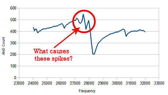
When I cut/paste data into LibreOffice and plot the results, there's an unaccountable spike in the data right at the resonance point. This is reproducible and not a bug in the program so far as I can tell, and it needs to be addressed in order to get accurate transducer measurements.
I made a list of possible explanations, and am in the process of testing and eliminating each.
1) A bug in the transducer program
2) Arduino hardware not powerful enough or otherwise not suitable for excitation
3) Poorly chosen component values for the interface circuit
4) An artifact of using square waves instead of sine waves to energize the transducer
5) Defective transducer/artifact of the transducer
6) Some other explanation
(NB: The Y-axis scale is in AtoD counts, which is upside down from the normal impedance plot. Maximum AtoD voltage is minimum impedance.)

Horn is much longer than needed
I used the speed of sound in aluminum to calculate the proper horn length (1/2 wavelength), and then cast and turned down a step horn.
'Turns out, there's two speeds of sound in Aluminum, and I used the wrong one (*sigh*). The 6400 m/s value is the speed of sound in bulk material, but it's 5100 m/s in a cylinder. I have no idea why the speeds would be different for different geometries, but there are definitely two values cited on the 'net depending on which source you use. Looking at Lindsay Wilson's page as a comparison check indicates that my horn 25% too long.
Not a big issue, it only means I have to face off the horn to bring it closer to the required length. I should also shorten the casting form.
Attaching horn to transducer has no effect
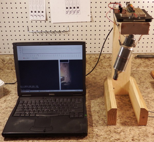
I wrote a program for the PC which triggers the frequency sweep and pops up a chart (like the one shown above) so I don't have to keep cutting/pasting data into LibreOffice to see the results. This means I can take my laptop to the hackerspace and shorten the horn using their lathe, then quickly see what this does to the resonant frequency. Hit uparrow/enter and it automatically triggers the sweep.
(I'll put this program up on GitHub along with everything else.)

...and come to find that shortening the horn has no effect on the system resonance. Possible explanations:
1) Horn face is not flat, not making good contact with transducer
2) Problem with interface/electronics/program (see above)
3) Defective transducer
4) Other explanation
I Need a better way to mount the horn in the lathe
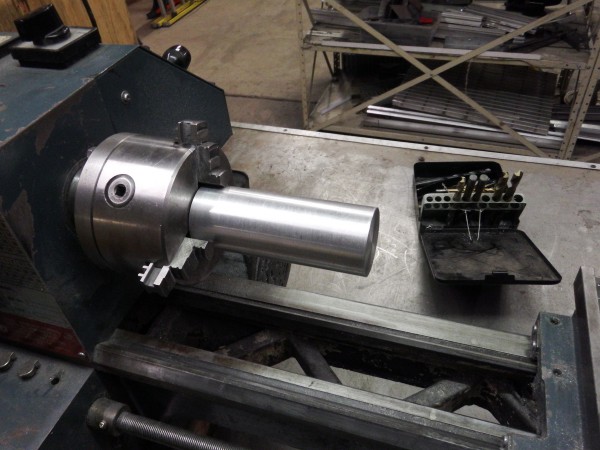
Learning to use the lathe has been a journey of discovery. I can hold the horn by either end in the chuck to face off a section (for tuning), but in doing so there's nothing holding the faced end. I can't use a tailstock center because it gets in the way of the facing operation. I can't mount the horn further into the headstock because it's too big for the hole in the middle. The steady rest badly(!) chews up the surface.
Also, the lathe 3-jaw chuck bites into the end of the horn. This is not an issue for the horn, but it'd be nice to be able to make professional-looking turned items.
So far I've been getting by on guts and liquor, but I really need a better solution. Possible solutions include:
1) Cut out wooden vice jaws and clamp the horn in the/use the Bridgeport mill for facing with a fly cutter.
2) Make/get a steady rest that uses bearings instead of brass fingers
3) Hold the horn by the small end in my hexagonal collet form
4) Find a bigger lathe
The image below illustrates the problem using the 1:1 step horn, which doesn't have a skinny end. For the step horn I have to clamp the skinny end in the chuck and face the fat end hanging out in empty space. The horn doesn't fit any further into the chuck.

Power supply from eBay is all busted up
The power supply I ordered from eBay is a bit... pre-owned.
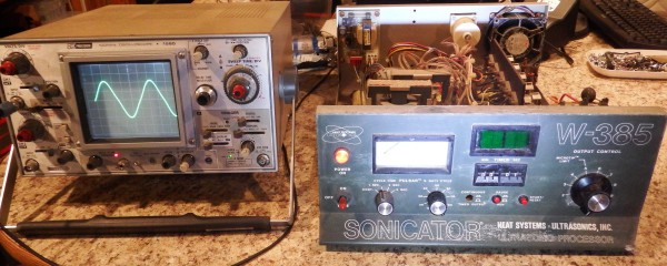
Pretty much all of the front panel controls are busted in some way or another: the power switch is broken permanently in the "on" position, two of the latching PB switches are jammed or broken, and the digital display doesn't light up. The connectors in the back are rusted, and the outsides are covered with a fine white powder, which I'm privately hoping doesn't turn out to be poisonous or carcinogenic. The insides show signs of severe rusting, as if the unit has been outside for several months.
The good news is that despite all this, the system seems to work. It fires right up and generates a perfect sine wave. With the power control set to minimum the output sits at 200 volts. Yow!

 Peter Walsh
Discussions
Become a Hackaday.io Member
Create an account to leave a comment. Already have an account? Log In.