Finally, a solution!
I have driven electrons into resonance, and I can hear the lamentations of their women! Bwahahaha!
.) I have a solution to the problem that has been vexing me for weeks.
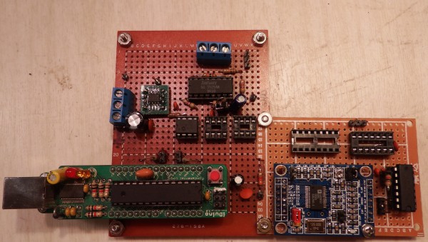
.) I'm confident I can make working boards (PCB layout, etc.)
.) The new driver is simpler and less expensive
.) The new driver can power transducers from 20 kHz through 40 kHz.
.) The new board will include measure and tune functionality, previously on a separate board
Statement of the problem
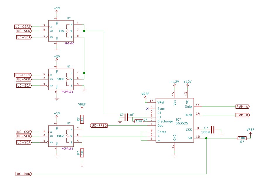
The UC3525 PWM controller uses an RC for timing. This is an analog frequency generator, and is subject to (frequency) drift from factors such as noise and temperature variations.

To compensate, the R of the RC circuit uses a digital pot controlled by a microprocessor. In theory, the micro adjusts the pot as needed to make the output frequency match the requested frequency.
This worked on paper and in prototype. The micro reliably kept the output within 1 Hz of the requested frequency with no transducer attached.
For outputs greater than 50 watts however, the noise affected the control and measurement systems, causing the frequency to drift faster than the control algorithm could keep up.
As the frequency swept around, the transducer would go into and out of resonance, which varied the power faster than the power tracking system could compensate.
So to summarize, the system couldn't maintain a stable frequency or power output.
Digital frequency FTW
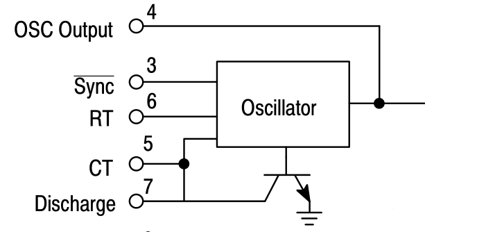
The new circuit uses an AD9850 to generate extremely accurate frequencies with 32-bit resolution. This solves all of the horn tuning problems caused Arduino generated frequencies: The Arduino only makes square waves and at poor resolution, the AD9850 solves both of these problems. In a previous build log I noted that the SG3525 has a SYNC input that can slave chips to an external frequency. (And apparently no one has ever used this feature.)
On a whim I routed the extremely accurate AD9850 output to the SYNC input and... it works! It's completely stable to over 150 watts.
The SYNC input is thus digital, with noise immunity per the static discipline.

It's also "set and forget", so the micro no longer needs a frequency-following system, or even a frequency *measuring* system. This greatly simplifies the software.
And as a bonus, the AD9850 goes from DC to 2MHz, which means the system should run other transducers such as the 20 kHz and 40 kHz types.
There's some devil in the details, but I feel confident I can design a board that's simple, stable, and easily controlled.
 Peter Walsh
Discussions
Become a Hackaday.io Member
Create an account to leave a comment. Already have an account? Log In.
Bravo!!
Are you sure? yes | no