Peter Walsh
-
Measuring resonant frequency, the easier way
04/04/2015 at 04:35 • 7 commentsTL;DR
A few passive components and an Arduino can measure the resonant frequency of a transducer in an automated fashion. This will come in handy when tuning the horn.
The circuit schematic is at the bottom of this post, and the program will be available on GitHub presently. Feel free to skip the gory details.
NB: As an experiment I am posting the circuit design in the style of an academic exercise in great gory detail, and I'm looking for feedback on presentation and style. Please help me out. If you think this is tedious and wasteful and too simplistic or something let me know and I'll adjust the style in future logs.
Measuring resonant frequency, the easier way
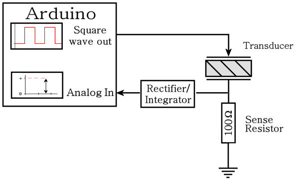
If you don't have a sweep frequency generator and/or a scope and frequency counter you can use an Arduino to measure the transducer resonant frequency. We'll need to do the measurement several times to tune the horn, so it makes sense to have a way to do this with as little effort as possible.
The block diagram circuit looks like this:
![]()
But before we hook everything up, it's a good idea to see if this is likely to work.
Design question 1: Can the Arduino source enough current?
According to the Atmel 328P datasheet (table 28.1: Absolute Maximum Ratings) the maximum DC current per I/O pin is 40 mA.
Assuming a worst case scenario when the transducer shows zero impedance, a 5V output will push 50 mA through the 100Ω resistor, and that's too much for the micro to handle.
However, the high-level output of the micro is less than 5 volts. According to the datasheet (Table 28-1. Common DC characteristics), the minimum high-level output is 4.2 volts with no "typical" or "max" values specified. Actually measuring the Arduino shows the output as 4.2 volts, so the measurement circuit will draw only 42mA .
And since a square wave is only high for 50% of the time the effective current is cut in half, so the DC current is actually 21 mA.
This is well within the rated 40 mA, so it looks like the Arduino can supply the necessary current.
Design question 2: Can the Arduino generate a fast enough frequency?
The fastest clock prescaler in the Arduino is 1-to-1 with the CPU speed, which is also the crystal speed, which is 16 MHz.
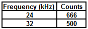
The resonant frequency of the transducer is nominally 28±1 kHz, so supposing we want to sweep between 24 and 32 kHz, the number of ticks per squarewave cycle is:
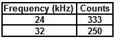
Each square wave cycle has two parts: one counter cycle of high output, followed by one counter cycle of low output, so the actual counter values to generate the square waves are:![]()
![]()
This seems reasonable. We can set timer 1 to one of these values or anything in between, set the OCR1A output to "toggle on counter reset", and the system will automatically generate a squarewave output.
Design question 3: Does the Arduino have enough frequency resolution?
Looking at the fastest frequency (250 counts, 32 kHz), we note that the next lower frequency will be 251 counts which generates 31.872 Hz, for a difference of 127.5.
Looking at the slowest frequency (333 counts, 24024 Hz) the next higher frequency will be 332 counts which generates 24096 Hz for a difference of 72 Hz.
So we can expect the Arduino to test and measure frequencies in steps of about 100 Hz.
This isn't great resolution, but it's comparable to what you can get using an analog signal generator and a steady hand.
There's a way to get much better resolution by doing extra processing in the micro, but I'll leave that for a later post. For now this should suit our needs.
Designing the rectifier/integrator
The transducer will turn the square wave into a sine wave which goes both above and below the ground plane. We need to block the negative half and convert from AC to DC before connecting to the analog input.
(Any input of the Arduino will be damaged by a negative voltage, and the AtoD only measures DC.)
So, something like this:
![]()
Design question 4: What values of R and C should be used?
Now we need to choose values for R and C.
Looking at the frequency/count table above, a full frequency sweep will test 250 through 333 counts inclusive, or 84 tests total.
For each test, if we generate the frequency for 0.1 seconds and then measure the AtoD, a full frequency sweep will take about 9 seconds, which seems reasonable.
So we need the integrator to settle down to its final voltage within 0.1 seconds, which means that the time constant has to be short relative to that value. Perhaps 1/10 of that, so T = RC = 0.01 seconds.
So reasonable values might be 0.1 uF for C and 100K for R.
Design question 5: Will ripple be a problem?
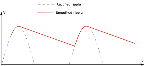
Converting AC to DC leads to voltage ripple in the output waveform. The capacitor will charge in response to an AC pulse, then discharge when the pulse goes away. The end result is a slightly varying DC voltage, and the AtoD will see different values at different times. We need to see if this will be a problem.
![]()
We can estimate the ripple by thinking of the capacitor discharging through the resistor after the voltage passes the AC peak.
Starting with "Ohms Law" for capacitors:
We can rearrange this as:
(T, being time, should be lower case here, but I can't seem to convince the HAD Latex editor to do that. Please bear with it.)
The dt term is the time between pulses, which is 1/frequency. The worst case in our frequency sweep is 24 kHz, for which the pulses arrive in 42 uS intervals (longest time between pulses, resulting in the longest decay time).
The current term "I" is the current taken away from the capacitor by the resistor, which is V (at the peak) divided by R. Substituting, we get:
We noted previously that the maximum voltage is about 4.2 volts, minus the voltage drop of the diode (0.7 volts), so the worst cast voltage peak should be about 3.5 volts.
And we supposed previously that our time constant T = RC is about 0.01 seconds, so plugging everything in we get:
Since our peak voltage is 3.5 volts, that's a ripple voltage of 1 part in 238, or about 0.5%.
The Arduino AtoD input has 10 bits of precision, and so can measure as little as 1 part in 1024. The ripple voltage should be within the lowest 2 bits of the AtoD converter.
In reality the peak voltage will be less than 3.5 volts since the transducer will never have zero impedance, and this will make the ripple voltage a bit less than calculated.
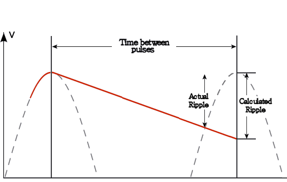
Also, we approximated the ripple by assuming that the capacitor would discharge over the full time period. In reality, the capacitor only discharges to the point where the next pulse arrives, as shown here:
![]()
We also played fast and loose with the differential in the equation above by breaking it into two pieces. In reality the capacitor discharges exponentially (not linearly, as shown), but this works out in our favor because beyond the first moment of discharge the capacitor discharges more slowly than calculated.
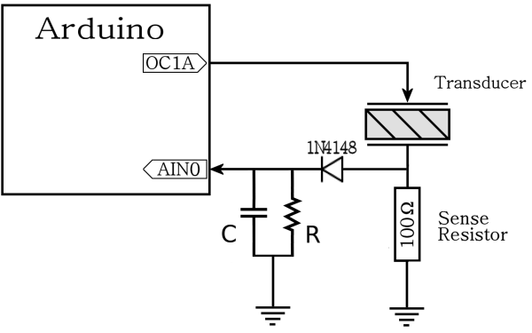
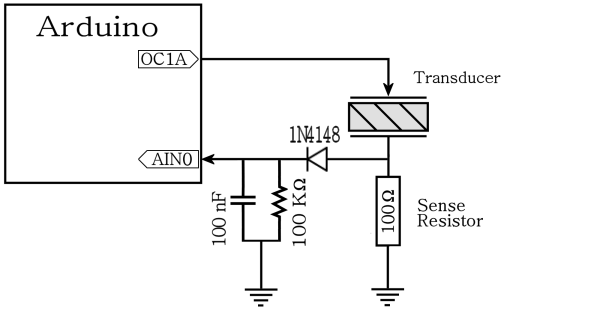
The final circuit:
So the final circuit looks something like this:
![]()
I checked the output using a scope, and found not a hint of ripple. More importantly, the output doesn't look like it will damage the Arduino.
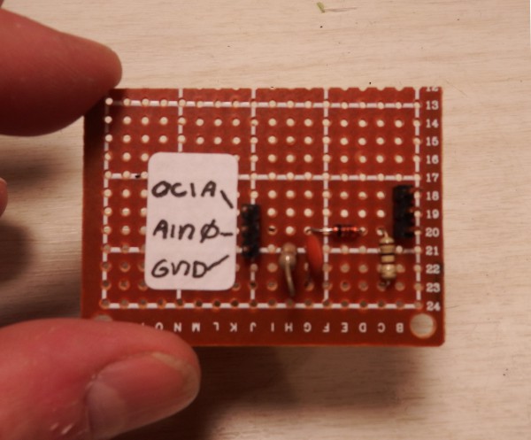
A little bit of perfboard, and here's the final result:
![]()
-
Progress report
03/31/2015 at 19:02 • 0 commentsI won the first interim prize! Woot! Thank you Mike, and everyone who brings us Hackaday - you people rock!
I've made much progress despite not having any logs to show for it. Mainly due to catching the flu, and then having to catch up from not doing things while having the flu.
====
On a whim I ordered an ultrasonic cleaner power board from eBay to see if it held any value to the hobbyist.
To my complete surprise, it came with a 100 watt transducer and instructions! This appears to be an error on the part of the vendor (beliefing), but they didn't respond when I msg'd them about it so... thanks eBay!
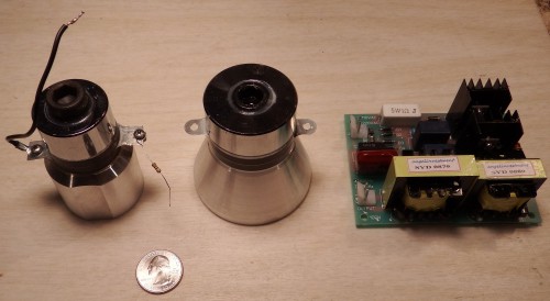
Here's the new transducer and supply, along side the original (50 watt) one for comparison:
![]()
I *think* the power supply is insufficient for our needs - the instructions say the board will overheat if the transducer is not attached to anything. With nothing connected (ie - no water bath) the transducer oscillates at resonance, and probably draws too much power from the board.
In other words, the unit can't actually supply 100 watts without overheating. More on this later, once I've had a chance to analyze the circuit.
====
I wrote an Arduino program to generate square waves and automatically measure the resonant frequency of transducer/horn assemblies. This is the "lazy" way mentioned in the previous post, and uses hardware that's more readily available to the hobbyist (ie - an arduino). If you don't have a signal generator or frequency counter (or scope), then an arduino or similar should work. This will be in the next log.
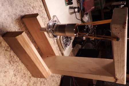
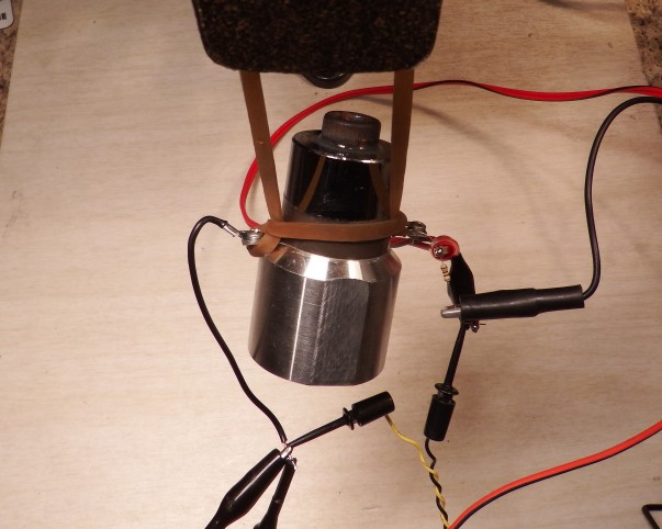
I also built a jig to suspend the transducer/horn while measuring resonance. A solid connection would cause the system to resonate at a different frequency.
![]()
====
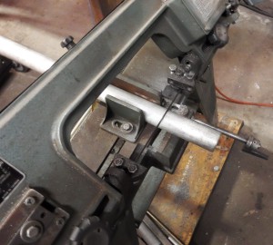
And finally, I managed to score a 4' long 1.75"" diameter aluminum rod from the local metal recycler (for $0.80/lb), which means I can cut horns for the small transducer as needed without going to the trouble of casting them.
(The big transducer has a considerably wider end, and will probably require cast'ed horns. I'll be describing this process in a future post.)
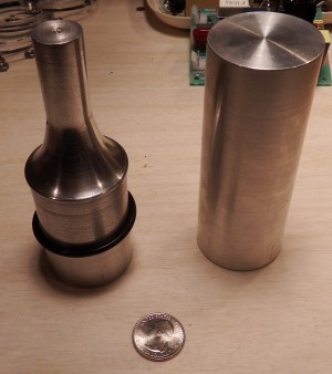
Here's some pics of the rod, and a 1:1 step horn made from it. I've got a particularly evil idea that I'd like to try using the 1:1 horn once the power supply is up and running.
Please follow the project if you'd like updates when stuff is added.
![]()
![]()
-
Measuring resonant frequency, the easy way
03/26/2015 at 20:58 • 1 comment![]()
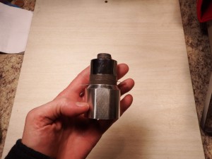
I bought a 50-watt Langevin-style transducer from eBay, which should be plenty for this application.
To make the tuned horn we need to determine the transducer's resonant frequency. There are two ways to do this: the easy way, and the lazy way.
Note: I am retracing the steps from Lindsay Robert Wilson's excellent website where he builds essentially the same device. If you don't understand something here, check out his site for a counterpoint description.
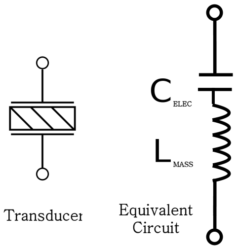
![]()
A piezoelectric transducer appears as a series-resonant L-C circuit. The electrodes on either side of the piezo plate form a capacitor, and the resonating mass acts as an inductance.
(It's actually a bit more complicated than this, but this is a good approximation.)
Driving the transducer at its resonant frequency achieves maximum power transfer from the transducer into whatever we're sonicating, so we need to determine what that frequency is. This will be useful when we design the power supply driver, and also when making and tuning the horn. More on those subjects later.
Measuring resonant frequency, the easy way
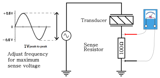
Current through the transducer is dependent on the impedance, which in turn is dependent on frequency. If we put a sense resistor in series with the transducer, the voltage drop will indicate the amount of current through the transducer.
At resonance, the impedance of the transducer is minimum and maximum current will flow. This same current causes a voltage drop in the sense resistor, and the maximum current (at resonance) will show the maximum voltage.
![]()
So to find the resonant frequency:
- Mount the horn so that it is not mechanically linked to anything (ie - hang it by rubber bands).
- Set up the circuit as shown.
- Set the signal generator for 1V p-p output.
- Adjust the frequency for maximum voltage.
- The frequency at which maximum voltage is seen is the resonant frequency.
![]()
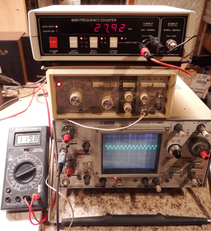
Here's my transducer hanging on a rubber band, connected to the electronics stack.![]()
And I get: 27,920 Hz.
You can use a multimeter (AC scale) or a scope to measure voltage, and a frequency counter or a scope to measure frequency. I'm using both methods to better show what's going on.
According to the transducer documentaiton, the resonant frequency should be 28,000 Hz, plus-or-minus 1 KHz.
So my transducer is definitely within spec, and I now have the information I need to create a tuned horn attachment.
-
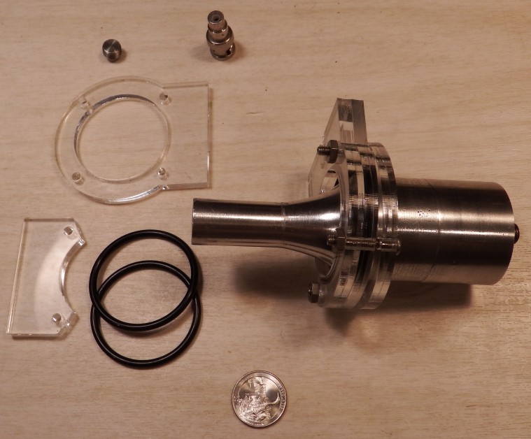
Horn complete, almost ready to test.
03/26/2015 at 05:45 • 0 commentsHere's my completed(!) horn and clamp. I am one step away from trying to sonicate some liquid, and once the flu stops kicking my butt I should have 4 more build logs and some code ready. Hopefully before the end of this weekend.
![]()
-
Initial Requirements
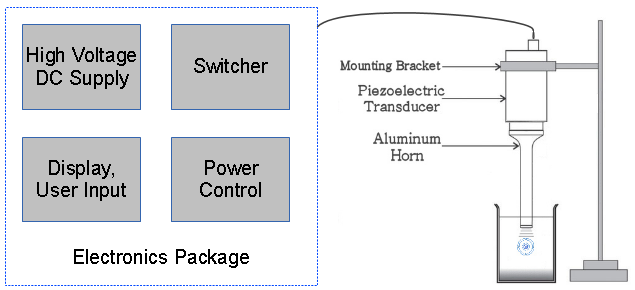
03/21/2015 at 00:24 • 0 comments![]()
I've identified 7 components for the project: four electronics functions (in one package, presumably on one board) and three physical pieces, as shown in the diagram. My initial requirements are:
High Voltage DC supply:
- Supply (TBD) volts
- Capable of 200 watts power
- Galvanically isolated
- Inexpensive/easily made
- (Optional) Low voltage output to power electronics
Switcher:
- Self-resonant (ie - automatically finds resonant frequency)
- Can control power of transducer
- Can measure transducer power
Power control:
- Measure power level of transducer
- Control power level delivered by switcher
- On/Off control of DC supply
- Timed on/off control of transducer
- (optional) Remote computer control
- (optional) Auxiliary relays for control of other equipment
Display/User Input:
- Show current settings
- Show timer countdown
- Allow user to set power
- Allow timed pulses
Piezoezoelectric transducer:
- Easily available
- Inexpensive
Horn/Sonotrode:
- Tuned to transducer resonant frequency
- Easily made (as easy as possible)
Mounting bracket:
- Electrically insulated from transducer/horn
====
I found this site describing making an ultrasonic drill... which is exactly what I plan to do! Woot!
His description is a little thin at places, so I will document the build process separately and in a different manner so that others will have both his and my descriptions for guidance.
I think his power supply circuit needs some changes, though (ie - as an instrument buildable/usable by others). It's fine for his uses, but I'd like something a little more automated and then I got an absolutely awful idea...
a perfectly wonderful, awful idea... and I need to do some experiments to see if it works and my inner Slytherin keeps saying "Bwa ha ha!" in the back of my mind.
There may be an easy, inexpensive way to build the HVDC supply using parts everyone has access to.
Stay tuned.
-
Results of Supeno's paper,
03/15/2015 at 22:56 • 0 commentsI've had a chance to look over Supeno's paper Sonochemical Fixation of Nitrogen in detail.
Quickly summarizing his results: Ammonia and various nitrate compounds (depending on supplied gases) are formed when the gases are bubbled up through water and sonicated. The rate of formation is very low, in the neighborhood of nanomoles per minute per watt, depending on reaction and conditions.
Other papers report similar rates of formation, with results ranging from tenths of nanomoles to micromoles per minute per watt (pages 9-11 in the referenced paper).
This is actually good news. If no researcher had seen formation of nitrates or ammonia in sonication experiments, this would mean that some fundamental principle invalidates the model. Since some formation was seen, then the model is correct at some level.
Additionally, the wide range of results (nanomoles to micromoles per watt) indicates that the model is dependent on experimental conditions, and this opens the possibility that the model could be explored in creative ways.
That said, a hobbyist-grade sonicator in the 50-100 watt range is an interesting project in it's own right, so I'm still intending to build one of those, and publish the designs.
======
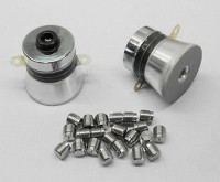
Ultrasonic transducers (normally used in cleaning baths) with power output up to about 120 watts are common on eBay, at a cost of about $20 - $50 depending on vendor and power. That's about right for a hobbyist unit, it's easily available, and shouldn't require extreme electronics for the driver (I think).
![]()
So I'm thinking: one of these transducers inside an H-bridge driver, a two hundred volt DC power supply, a microcontroller to generate frequency and control power, and a machined horn to transfer energy to the reaction chamber.
A small sonicator could be used for other hobbyist purposes such as plastic welding, cleaning, (possibly) spot welding, cell disruption, drilling, and probably a bunch of other things I'm not thinking of.
So even without the Nitrogen aspect, it's still an interesting project. To me, at least.
-
Ultrasonic power supply on eBay for $50
03/14/2015 at 02:57 • 0 commentsSome surprising (to me, anyway) developments.
I had originally planned to build an ultrasonic power supply with plans, schematics and whatnot, and come to find one on eBay for $50. This unit will supply 385 watts, which is much more than the 50-watt unit I had planned to build. And it will save me hours of designing, testing, and building.
![]()
After discovering that there are several names for what is essentially the same thing (thank you, eBay!), I redid my literature search and found this paper titled "Sonochernical Fixation of Nitrogen" where a graduate student at Ottawa does much of what I am proposing to do.
I haven't had time to read the paper in detail (only skimmed), but from a first impression of his experimental setup I'm guessing that he is not using a very high energy density (ie - the watts per square cm of his sonification is low), and he's sparging the gasses through a frit instead of using a pass-through probe with concentrator.
(It means he used a sort of aquarium air stone to bubble the gasses up through the solution. I didn't know either, I looked it up.)
So it *may* be that I'm looking in places where people have looked before, which means that my probability of success has dropped dramatically.
My original plan was to design a hobbyist-grade ultrasonicator that could be used for home sonochemistry experiments. That's a pretty interesting project in its own right, and I've always known that it's unlikely that I'll find anything.
Maybe in a few months will be the first "hackaday prize" entry featured as a "Hackaday Fail" :-)
-
Initial Todo list
03/11/2015 at 23:27 • 3 commentsPlease bear with me, as I am *just* getting started creating the project, backfilling information, and everything else.
I hope to spend the next 5 days fleshing things out.
Todo:
1) Get dokuwiki running on my home server. Install a good theme, flesh out the link/file structure and organization.
2) Write background pages on the Bosch-Haber process, and other possible processes and reference material.
3) Write up a project roadmap - what steps to take in what order
4) Come up with an appropriate project image
Improve the Haber process
See if ultrasonic cavitation can be used to fixate atmospheric Nitrogen less expensively than the Haber process.