Close
0%
0%

BLDC Variable Speed Water Pump

Increasing the chooch factor on an offshore water pump. Ladies and Gents, I give you Franken pump.

Public Chat
Similar projects worth following
In this project, I dissect a good ol' Harbor Freight pacific hydrostar water pump and completely transform it into a variable speed BLDC pump. In the process, I'll give it some extra oomph and just maybe, I'll end up with a usable pump at the end of this journey.

So here's the deal.... I was in need of a variable speed pump for an upcoming project I am working on that produced about 600 - 800 gph of flow on the high end and about 100 to 200 gph on the low end. 

Searching the usual corners of the internet yields some okay deals for your basic import Chinese pumps. Some had okay-ish reviews but it honestly looked like any decent variable speed pump was going to cost a decent chunk of money. - Plus just buying something isn't nearly as fun as building it!

The fundamental idea of this project is to end up with a variable speed pump using what I had on hand (excluding the 3D printed stuff of course). 

In the end, I achieved my goal and since I already had the parts on hand I cannibalized from other projects the total cost to me was almost nothing. 

For those of you who might want to do the same thing using the same parts I have.... Well, just go buy yourself a pump. The motor used in this project alone is the cost of a variable speed import pump. XD

Housing.STL

Main BLDC motor housing

Standard Tesselated Geometry - 3.15 MB - 02/04/2018 at 16:02

Download

Coupler.STL

Colling coupler for counterclockwise rotation

Standard Tesselated Geometry - 1.88 MB - 02/04/2018 at 16:02

Download

Coupler Mirror.STL

Cooling coupler for clockwise rotation

Standard Tesselated Geometry - 1.88 MB - 02/04/2018 at 16:02

Download

Flange Adapter.STL

Pump casing adapter for main housing

Standard Tesselated Geometry - 201.64 kB - 02/04/2018 at 16:02

Download

  • 1 × Pacific Hydrostar Clear Water Pump 3/4 Horsepower 650 Gph
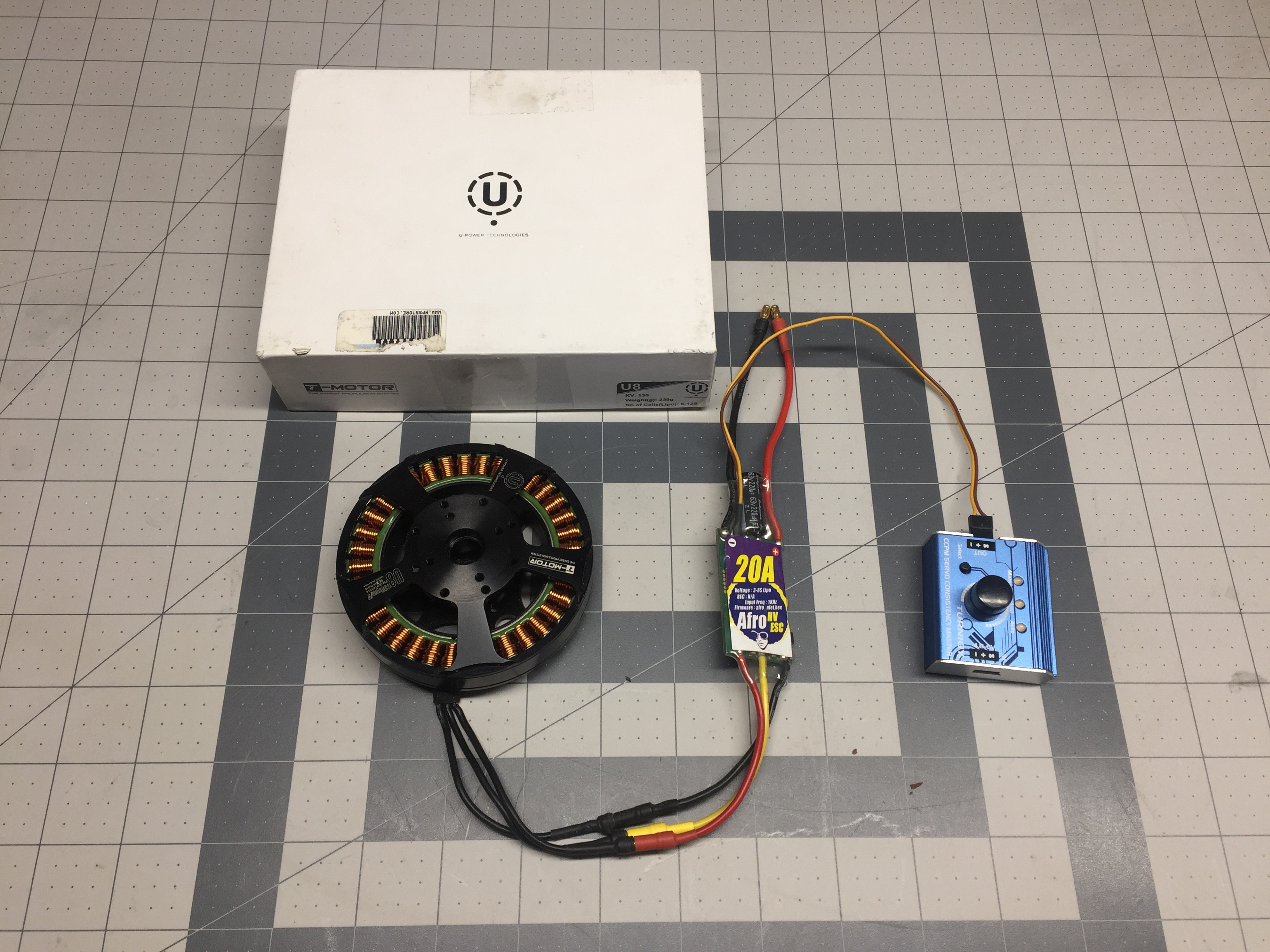
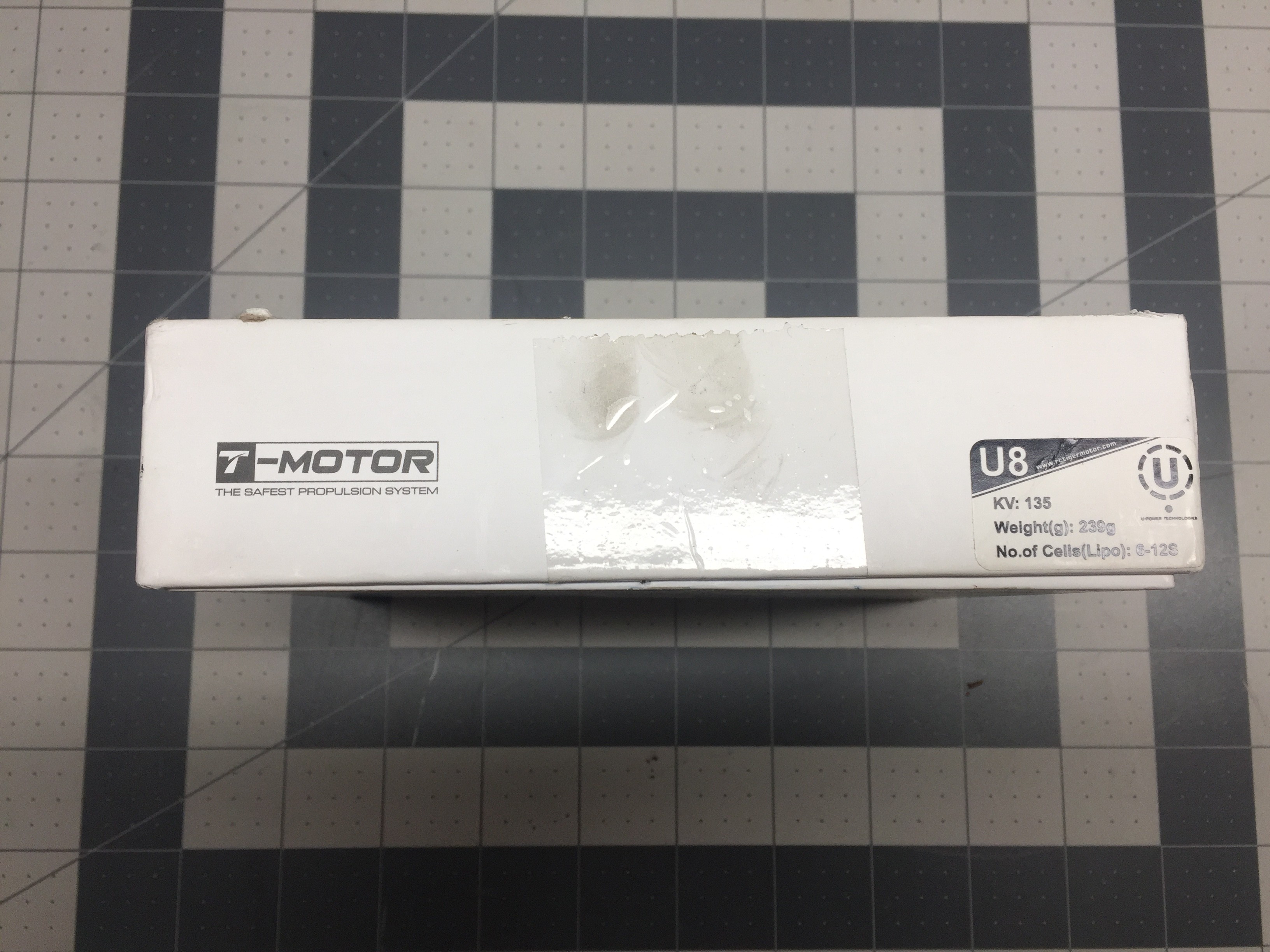
  • 1 × T-Motor U8 BLDC Motor
  • 1 × Afro 20Amp HV BLDC ESC
  • 1 × 3D Printed Motor Housing
  • 1 × 3D Printed Pump Casing Adapter Flange

View all 10 components

  • Chooch Factor Increased

    Andrew Mayhall02/10/2018 at 16:09 0 comments

    Hey everyone! 

    In this log I will successfully turn the dial up to 11 increasing the Franken pumps flow to 850GPH. 

    Everything is pretty straight forward. 36v 500 watt power supply. New HV ESC. 5 Gallons of water and a messy workbench... 

    Anyways, here is the most recent test! 

    I have ordered a 48V 800w power supply that should get me up to about 54v with the V-Adjust trim feature. The pump has already met and exceeded my specifications.... Now I just want to push it to the limit! because of.... well, science! 

    Hope everyone enjoys! 

  • Operation!

    Andrew Mayhall02/05/2018 at 01:25 0 comments

    So, this is the part everyone has been waiting for. Franken Pump drinks its first blood. And by blood I mean.... wait, Frankenstein doesn't drink blood... 

    Anyways! Horrible humor aside.. The operation of this pump is exciting! 

    It's probably easier for everyone to just watch the video. I'll shut up. 

    So the end results are pretty great. Approximately 643GPH at max flow using a 24V power supply. 

    During the planning section I calculated the BLDC motor would require about 26v to match the RPM of the original motor. This certainly accounts for the flow rate reduction. 

    I am trying to source a 36v power supply which should let me "over drive" the pump substantially producing a higher flow rate and potentially higher head pressures. The trade-off here will be the likely formation of cavitations on the impeller blades... But I'll worry about that at another time! haha

    Thanks again for sticking around during the build of this pump. Feel free to chime in on the discussions and  stay tuned for more updates! 

    Hope you enjoyed!

  • Assembly

    Andrew Mayhall02/04/2018 at 02:08 0 comments

    So you've made it this far with me. It's time we assemble the beast and bring Franken pump to life! 

    This was a very straight forward assembly almost boring perhaps. Surprisingly there were absolutely no major issues with my designs and subsequently the 3D prints. I assembled everything within 15 minutes of getting the prints in and had the pump spinning for the first time!

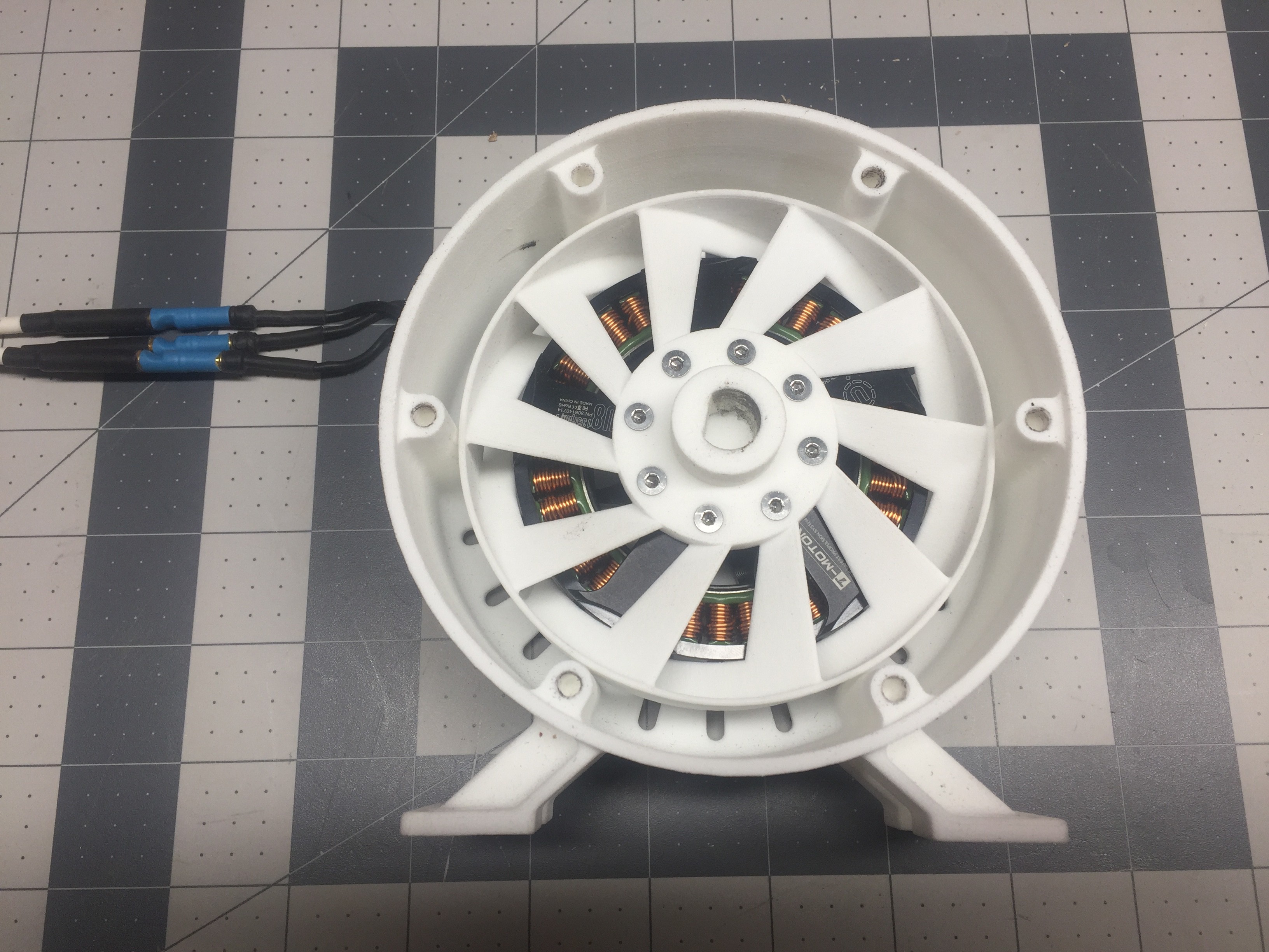
    I did forget to design in a designated cable exit and bend relieve for the cables exiting the BLDC motor. No trouble a quick session with the dremel could't solve. 

    Additionally upon assembly it became apparent that the pump casing is very heavy and a support bracket should have been made to help reduce the strain on the main housing.  Perfect job for the Makerbot here. 

    So I'll get on with the show! 

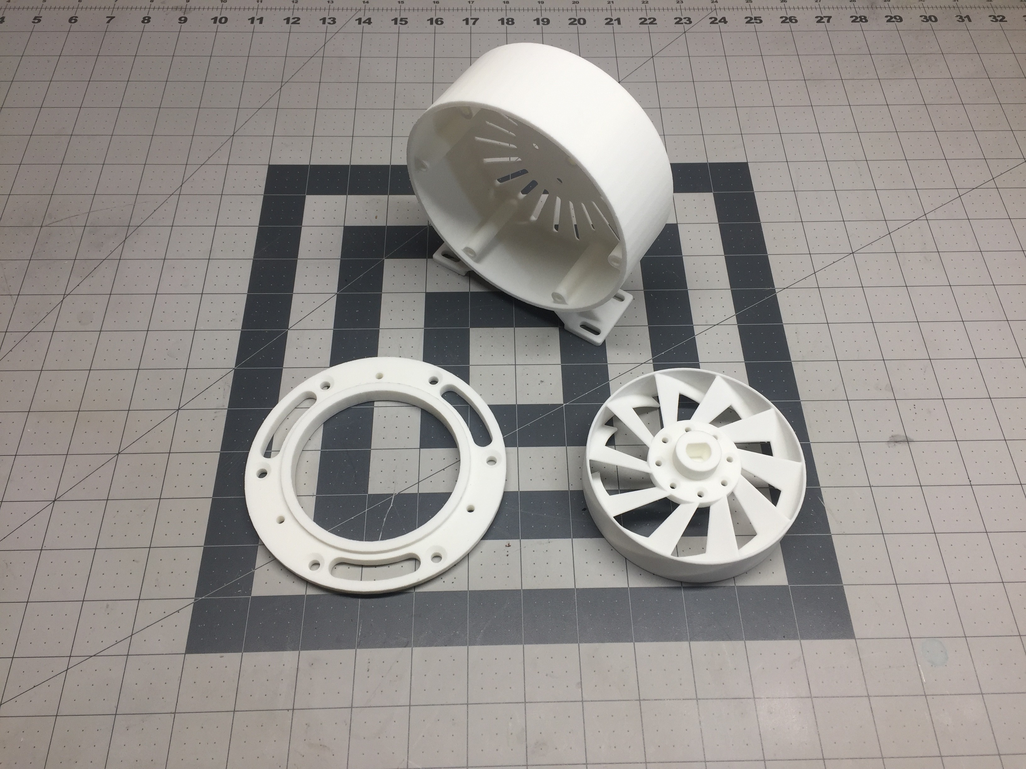
    Here are the parts as designed. These are printed out of SLS nylon using Shapeways. I actually had a gift card though them and figured this project was worthy of being printed in nylon so why not! Overall I think the parts came to just over $100. Not bad and considering I had everything in inventory so I'm "under" budget compared to an off the shelf variable speed pump! 

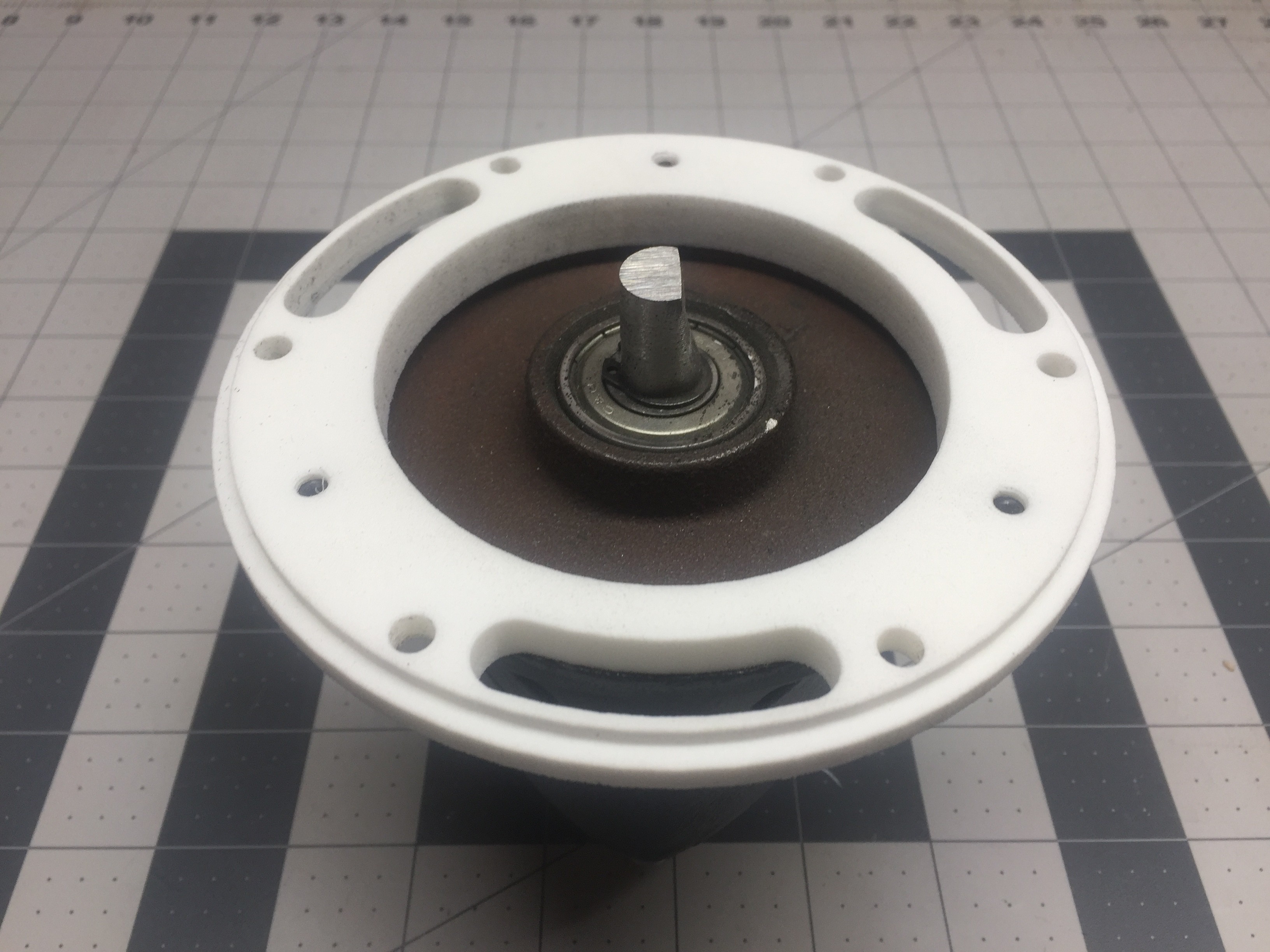
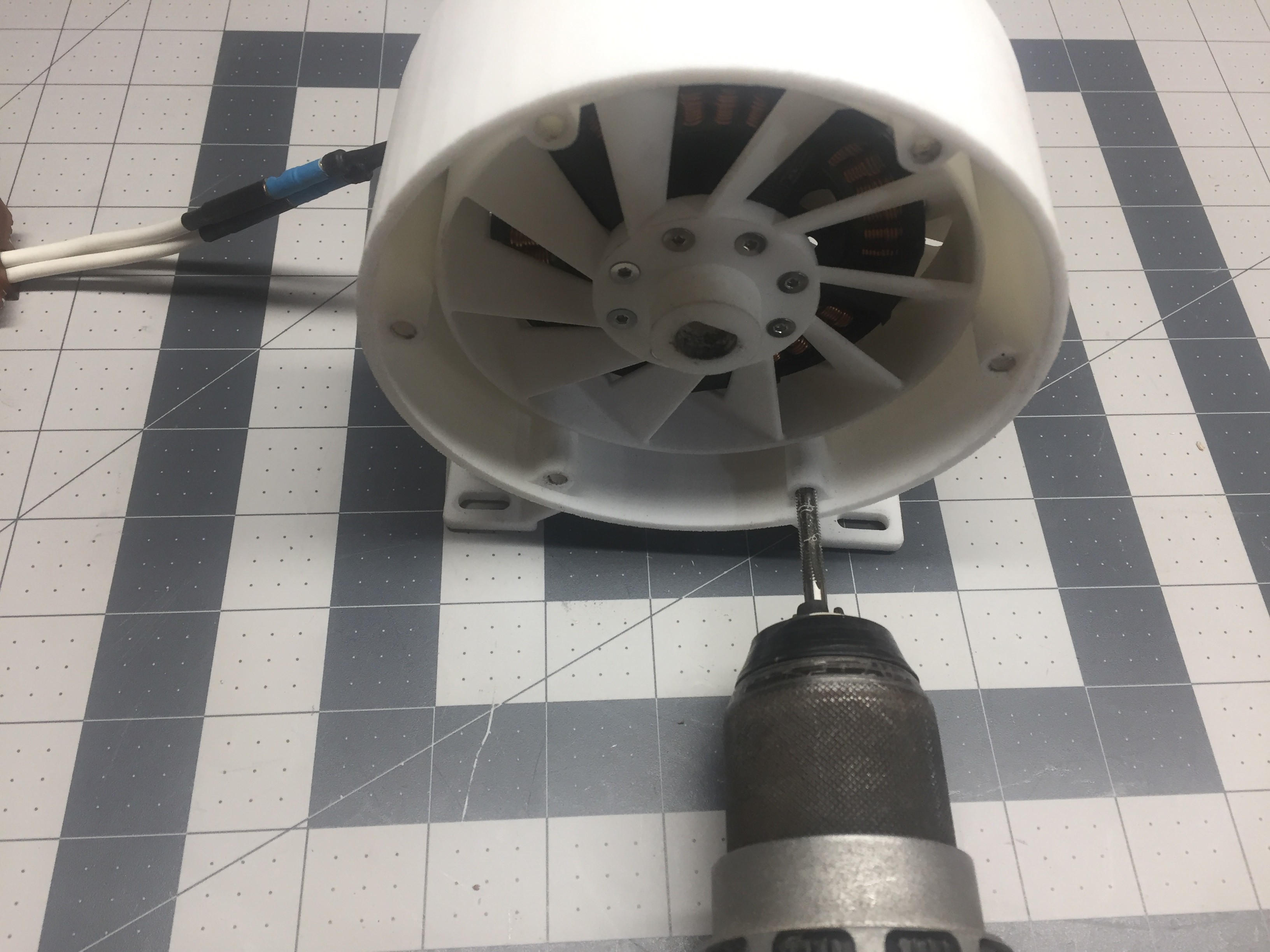
    First, I installed the adapter flange onto the pump casing flange. This is done by tapping 3 M5 holes into the pre-sized openings in the print.

    Next, I checked the fit of the coupler and the motor. - Perfect! Now its as simple as installing the 8 M3 flat head fasteners! 

    Now its time to install the motor into the housing. 4 M4 fasteners into the back of the BLDC motor and its almost complete! 

    Tapping the main housing is easy with a drill.

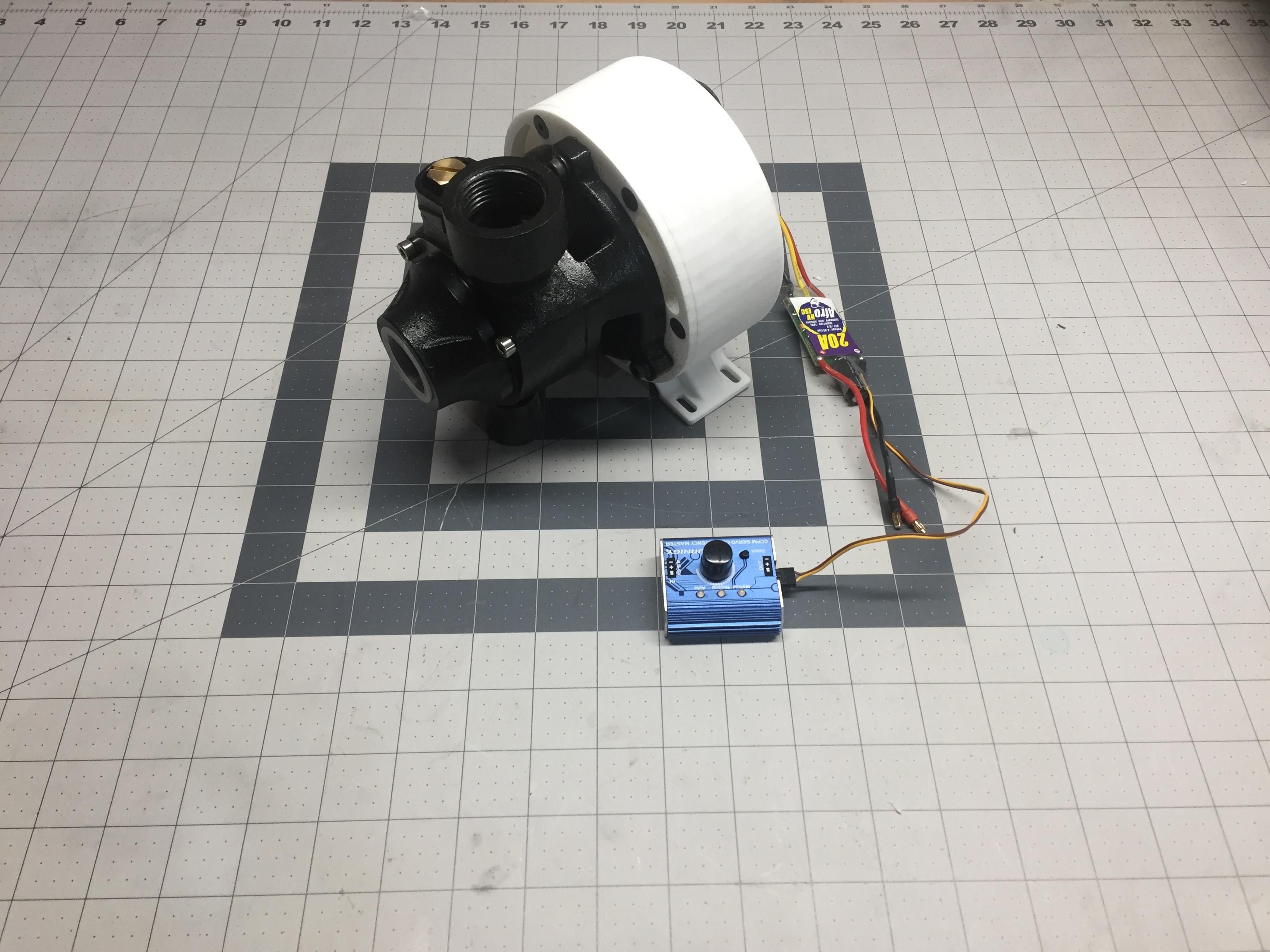
    Now, thats it! Franken pump is assembled and ready to test! 

    Below is a sneak peak of the first run. 

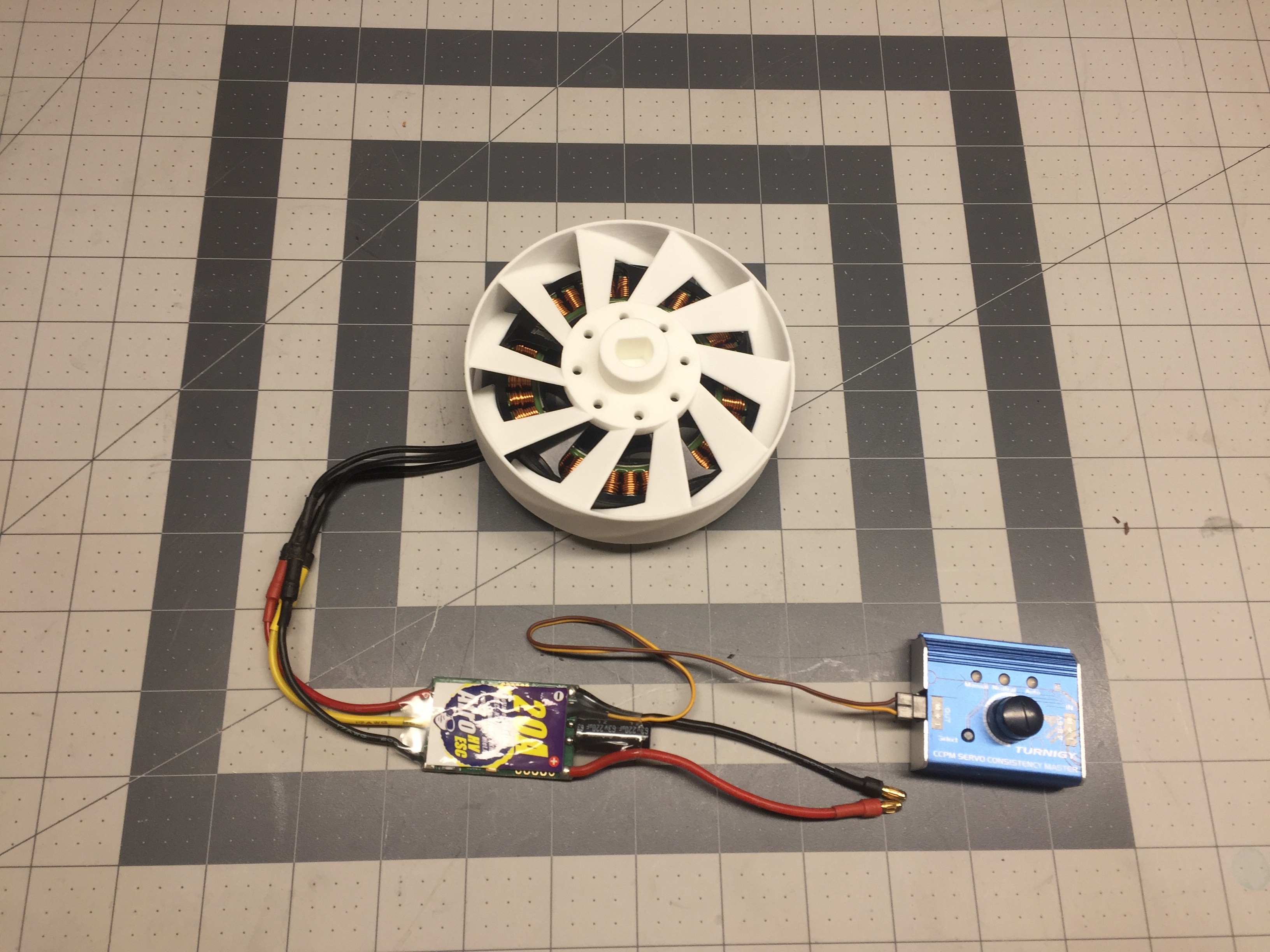
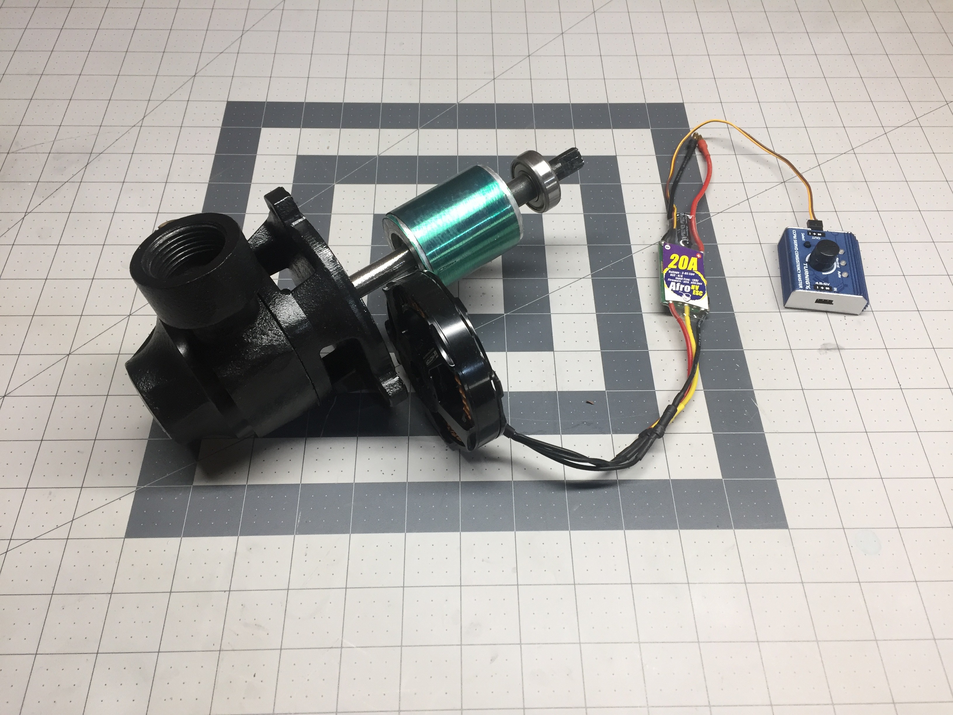
    I switched out the ESC controller because the Afro one didn't have a UBEC to power the PWM dial. 

    Franken pump runs very smooth. There are some minor vibrations but overall I think this project was a success! 

    Thank you everyone for following along! If you stick around for a bit longer my next update will show the pump in action and give some new performance metrics! 

    Stay tuned!

  • 3D CAD Design

    Andrew Mayhall02/04/2018 at 00:47 0 comments

    Alright! So in my last log I tore into the Pacific Hydrostar pump and got to the juicy insides.

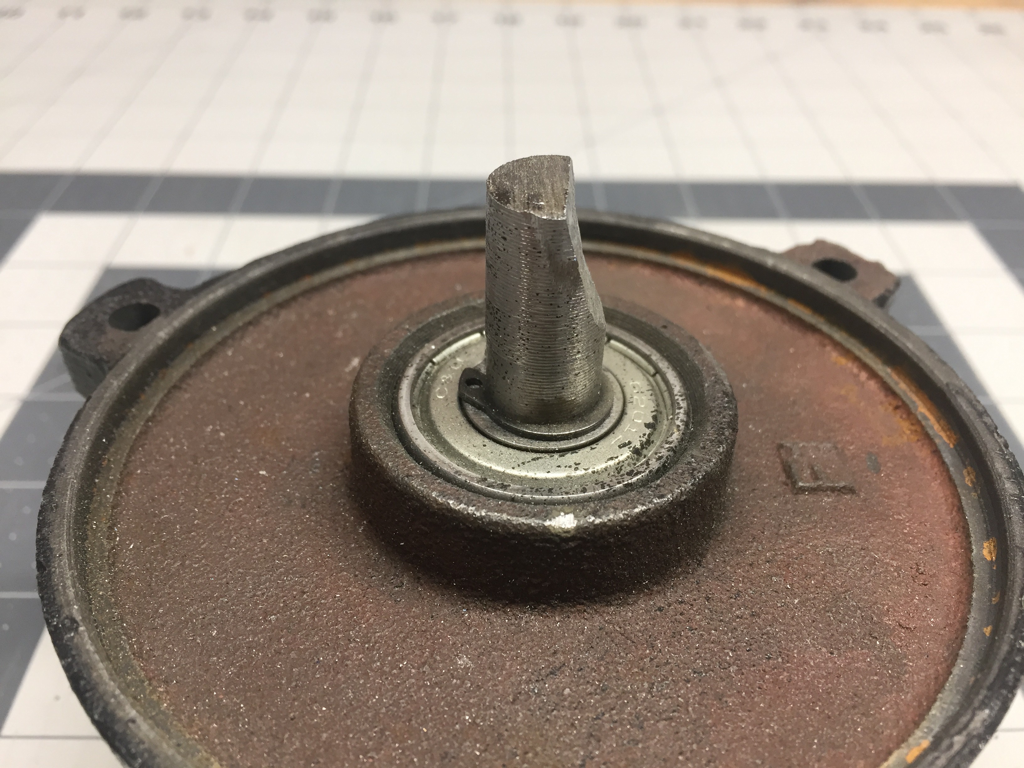
    First, I decided to go ahead and cut off the armature from the main shaft and then grind in a flat to create a D shaft. No turning back now! 

    Instead of going for just a flat D shaft I decided to angle the grinding so to provide a good positive stop where the coupler would be mating to the shaft. 

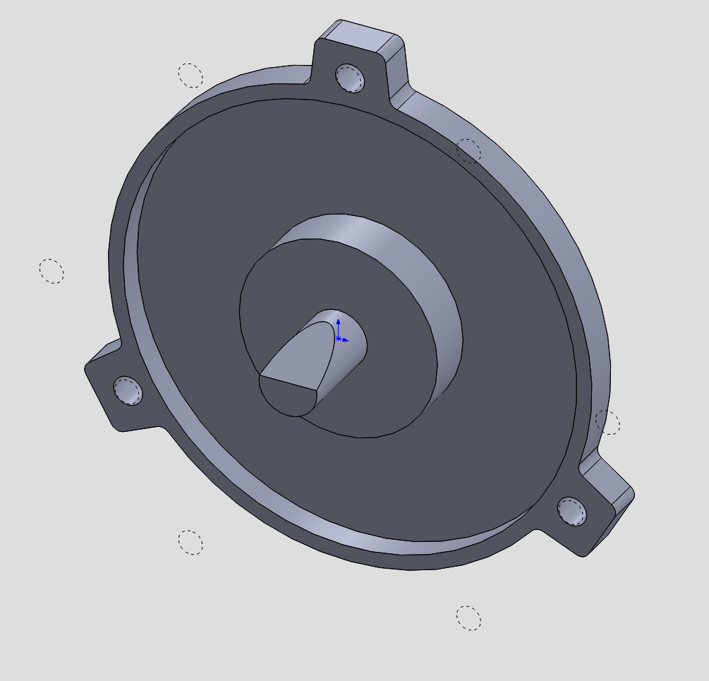
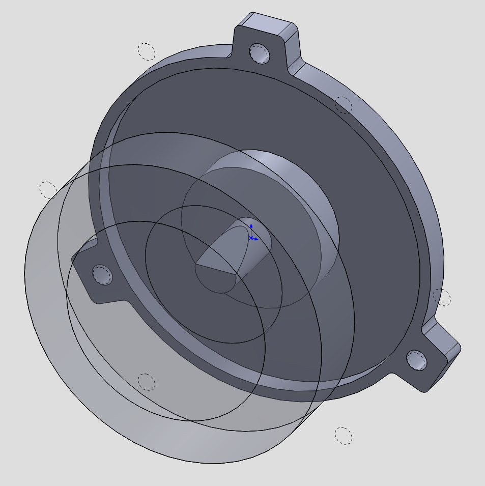
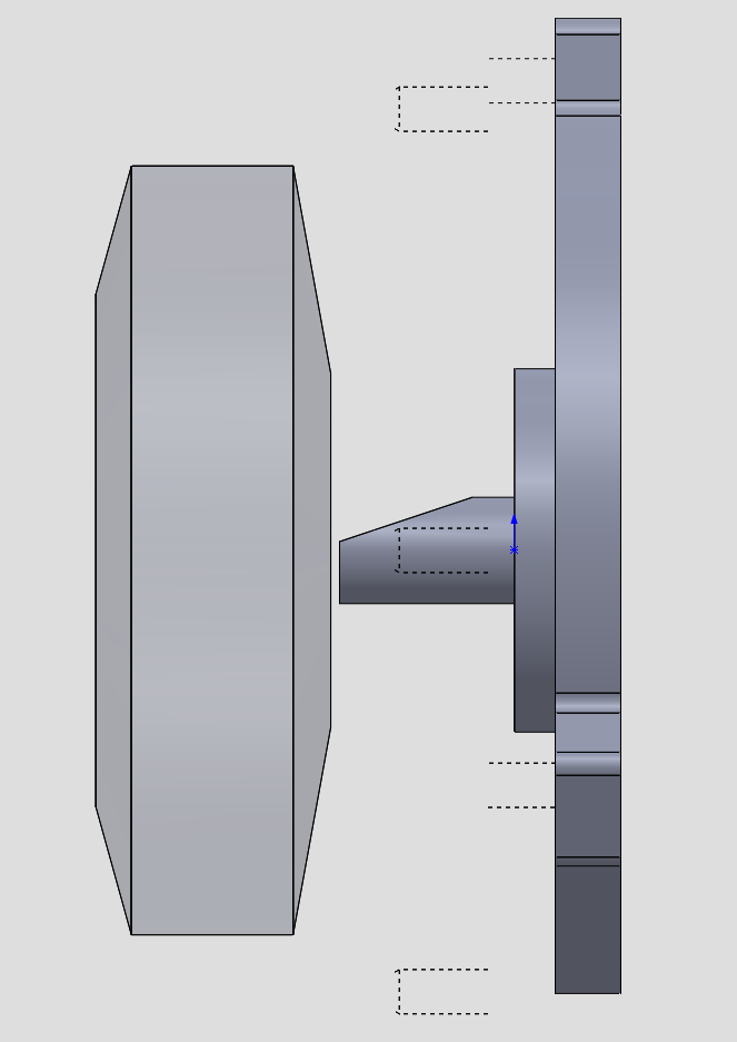
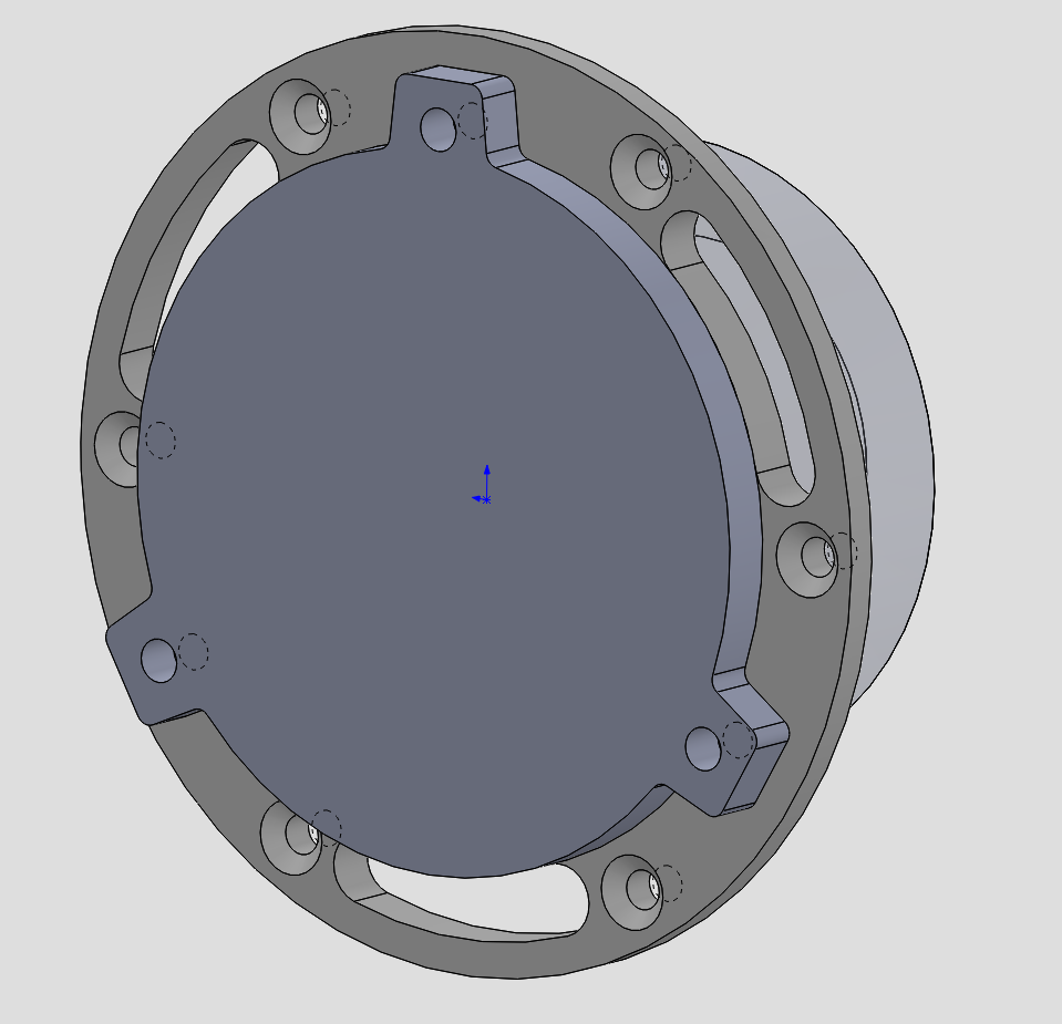
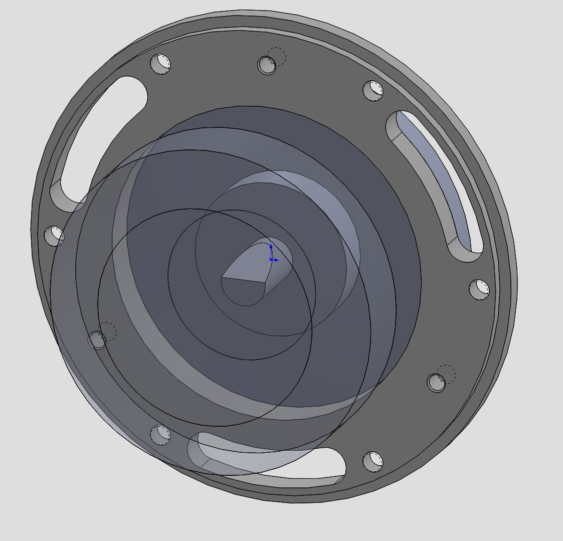
    Next I shifted focus to creating an assembly within solidworks and beginning the process of  working out the geometry of the coupler and come up with some sort of housing for the BLDC motor. 

    Once the pump was completely broken down capturing the necessary measurements was pretty straight forward. 

    Using just the essential information I proceeded to build a rudimentary mock up of the mounting flange for the pump casing. 

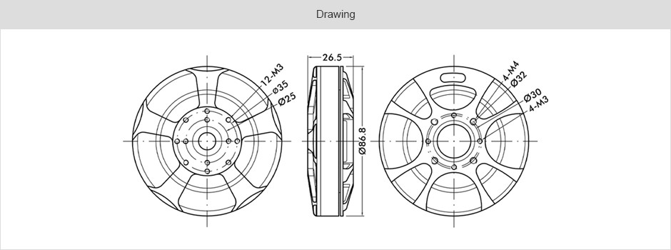
    Next, I needed to mock up the BLDC. Thankfully, T-Motor provided a technical drawing so this was very straightforward. 

    Here I have a rough approximation of where I would like the flange and motor to be positioned. 

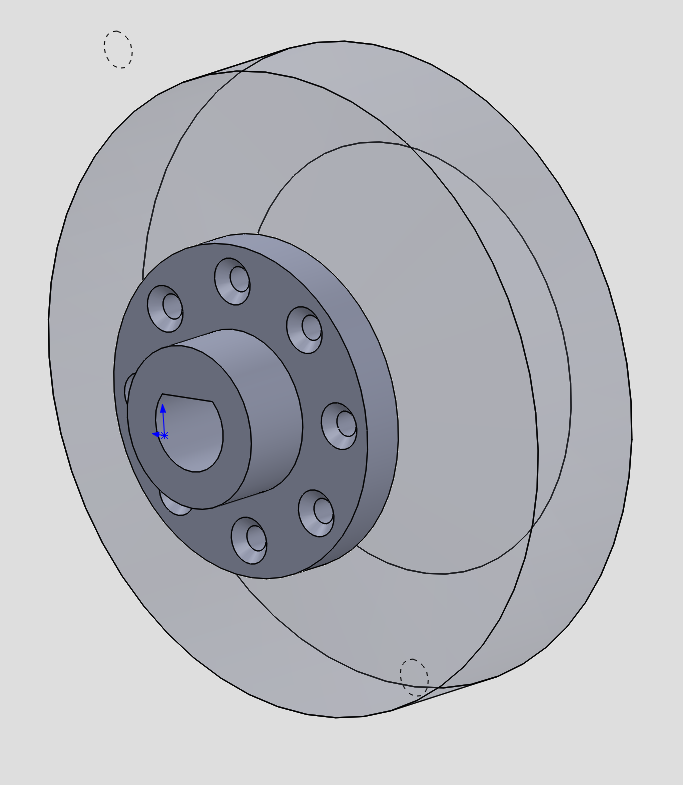
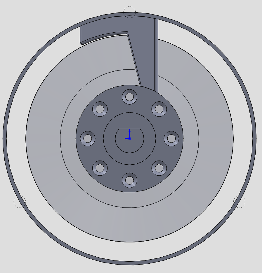
    Now I think this is a good time to consider various options for coupling the shaft to the motor. T-Motor provides a ring of 8 M3 tapped holes around a 35mm circle. They also provide a precision(ish) indexed hole of 13mm in the center of the motor. 

    I think the straight forward approach would be to make an adapter out of SLS nylon that features a locating pin of 12.95mm in the rear and a mounting flange for the 8 M3 fasteners. A collar would extend from that flange and encase the modified D shaft. 

    Overall, its a simple design that should work just fine. For my application I am not going to need the full output pressure of this pump and therefore I'm not really concerned about the stresses this coupler will be under. And hey, if it breaks I can just print another! 

    Before calling this part done I think it wold be important to address the cooling issue of this motor. Given that this particular motor is designed for multi rotor drones with big ass fan blades attached cooling isn't something that should be an after thought here. 

    There are a number of ways I can go about cooling this motor, from an eternal DC fan, to a simple paddle style centrifugal blower attached to the motor. 

    In this case, I saw an opportunity to build in a simple axial fan directly onto the coupler. This way, as the the motor would run cooling would be forced though the open stator of the motor providing cooling. 

    The design is pretty straight forward and an angle of 30 degrees should be adequate enough to move air though the motor. I'm not going for high efficiency here or an optimized design just something that will work and keep the motor from burning up! 

    One of the considerations I had to weigh was a trade-off of size. Specifically related to making the cooling fins the same diameter as the motor or extending them slightly to increase airflow. 

    On one hand, I don't anticipate needing the full power of this pump and the small cooling provided by simple fins should be enough to keep everything with boundary conditions. This would mean that I could keep the motor housing roughly the same diameter as the original motor and have a straight forward housing design. 

    On the other hand, adding extra cooling capacity would be beneficial if I ever wanted to increase the pumps output or potentially overdrive the motor slightly for whatever reason. Increasing the fin length would mean that I would have to add an adapter to the main pump casing flange to accommodate a larger diameter housing. 

    Ultimately I decided that the use of an adapter flange wasn't a big deal and opted for the extra cooling. (Boy does it work!)

    Since opting for the larger fan, the housing would need to be bigger too. This housing is designed...

    Read more »

  • Teardown & Planning

    Andrew Mayhall02/03/2018 at 19:16 0 comments

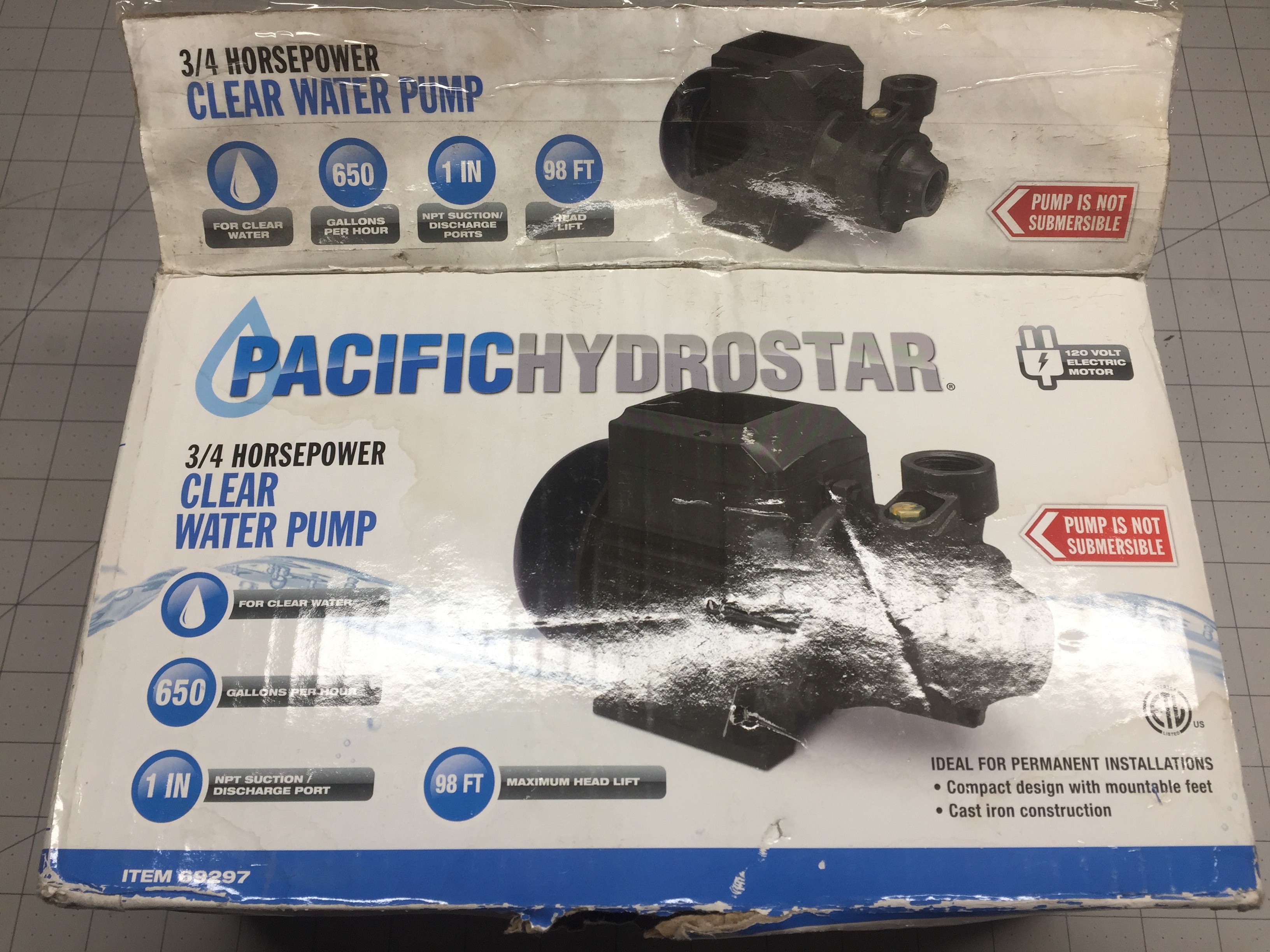
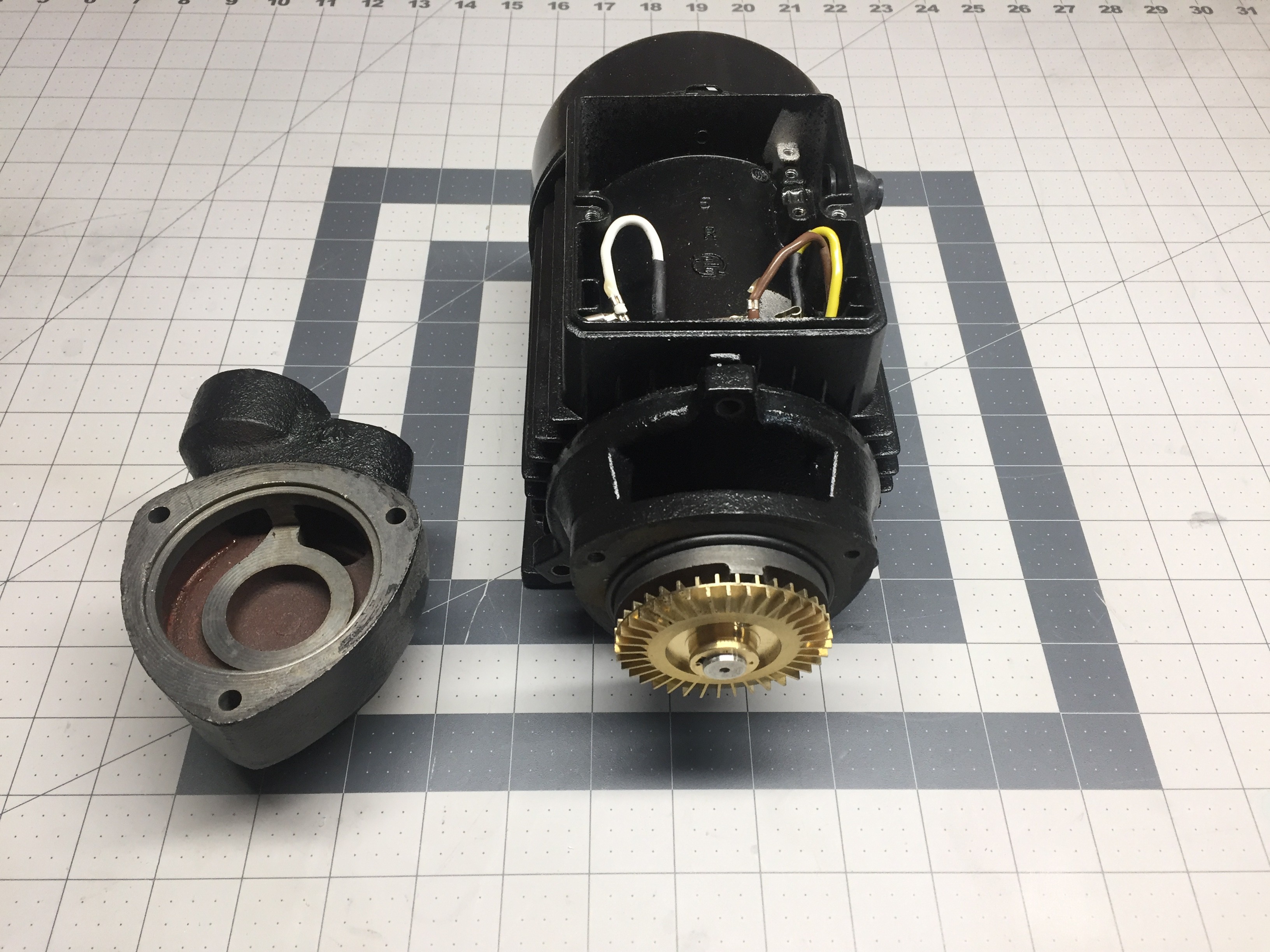
    Lets start off with the unsuspecting subject that will serve as the organ donor for this Franken pump project. The Pacific Hydrostar 3/4HP clear water pump

    I picked this bad boy up from Harbor Freight about 2 years ago for a parts washing station. If I recall correctly I think it cost about $50 - $60 new. Unfortunately, I never got around to building the part washing station so it has been sitting in my parts inventory forever.  

    Now that I have an upcoming project needing a pump of sorts, this is the perfect excuse to use it! 

    The pump is pretty basic... Cast Iron construction, split phase induction motor 1" NPT inlet and outlet connections, etc.

    The box advertises 98ft of head, and 650gph nominal. 98ft of head works out to be around 40psi. Surprisingly, unlike most Harbor Freight items, this marketing wank is pretty on par and perhaps a bit low. But I am positive we can do better! 

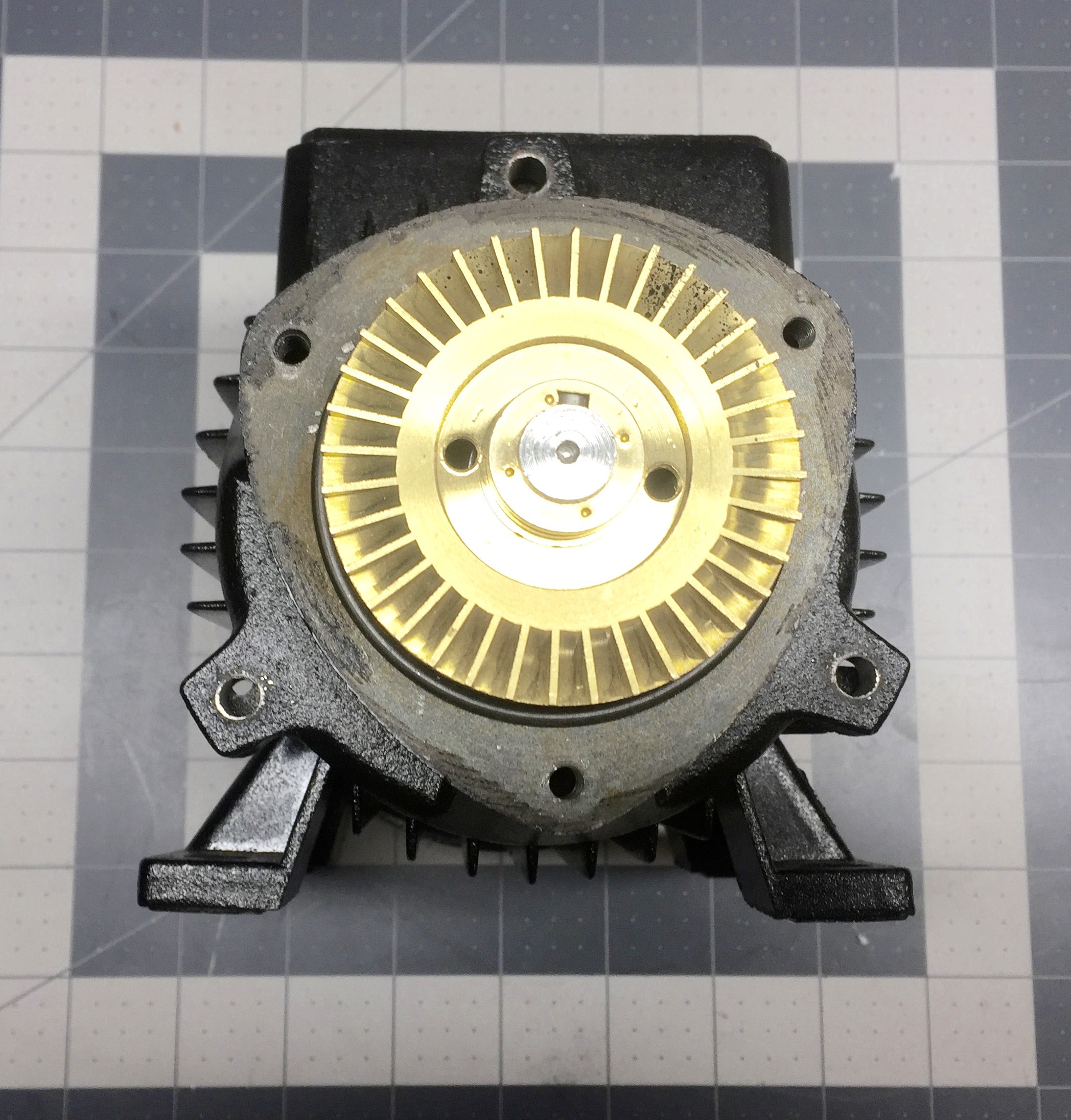
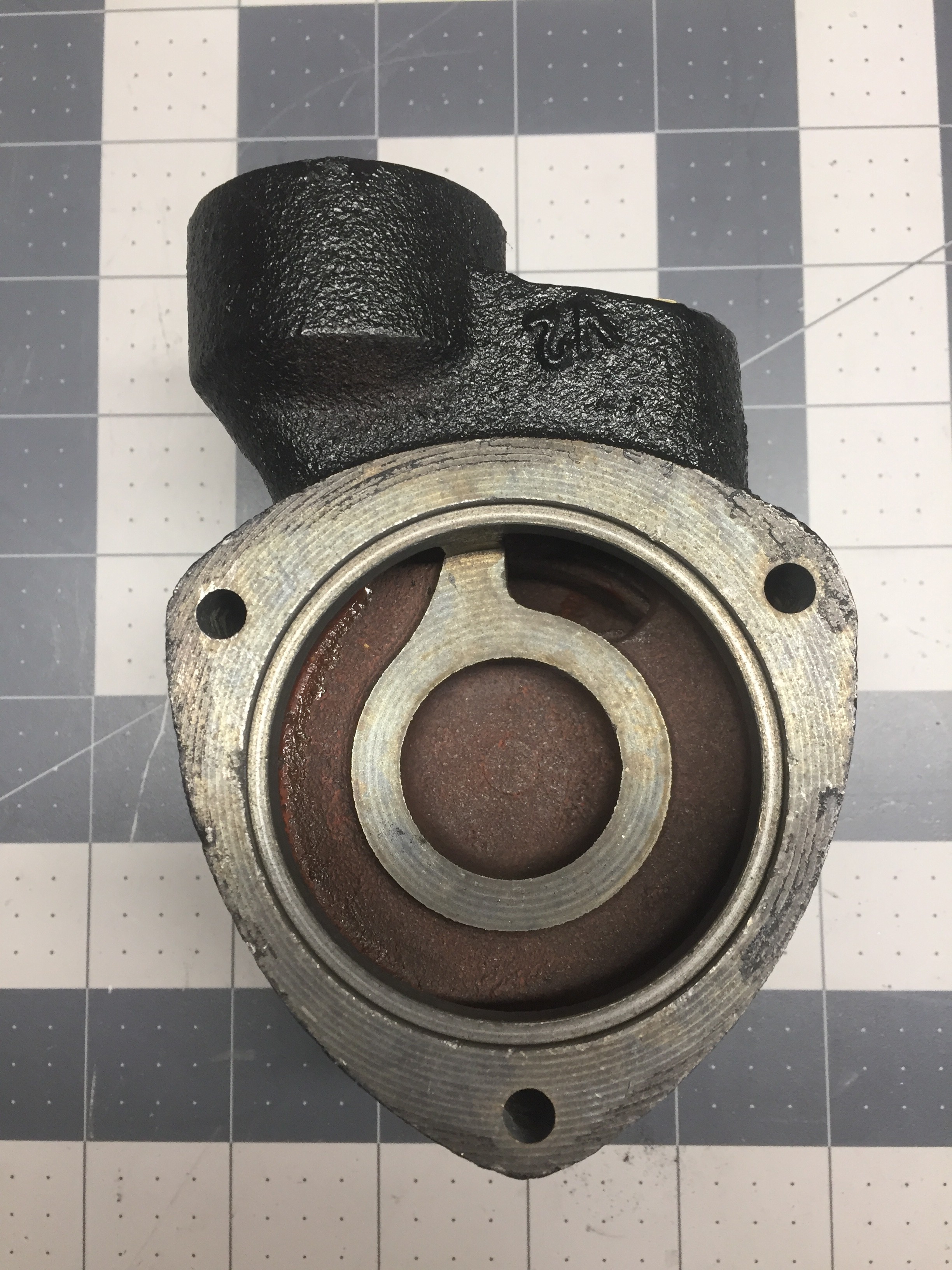
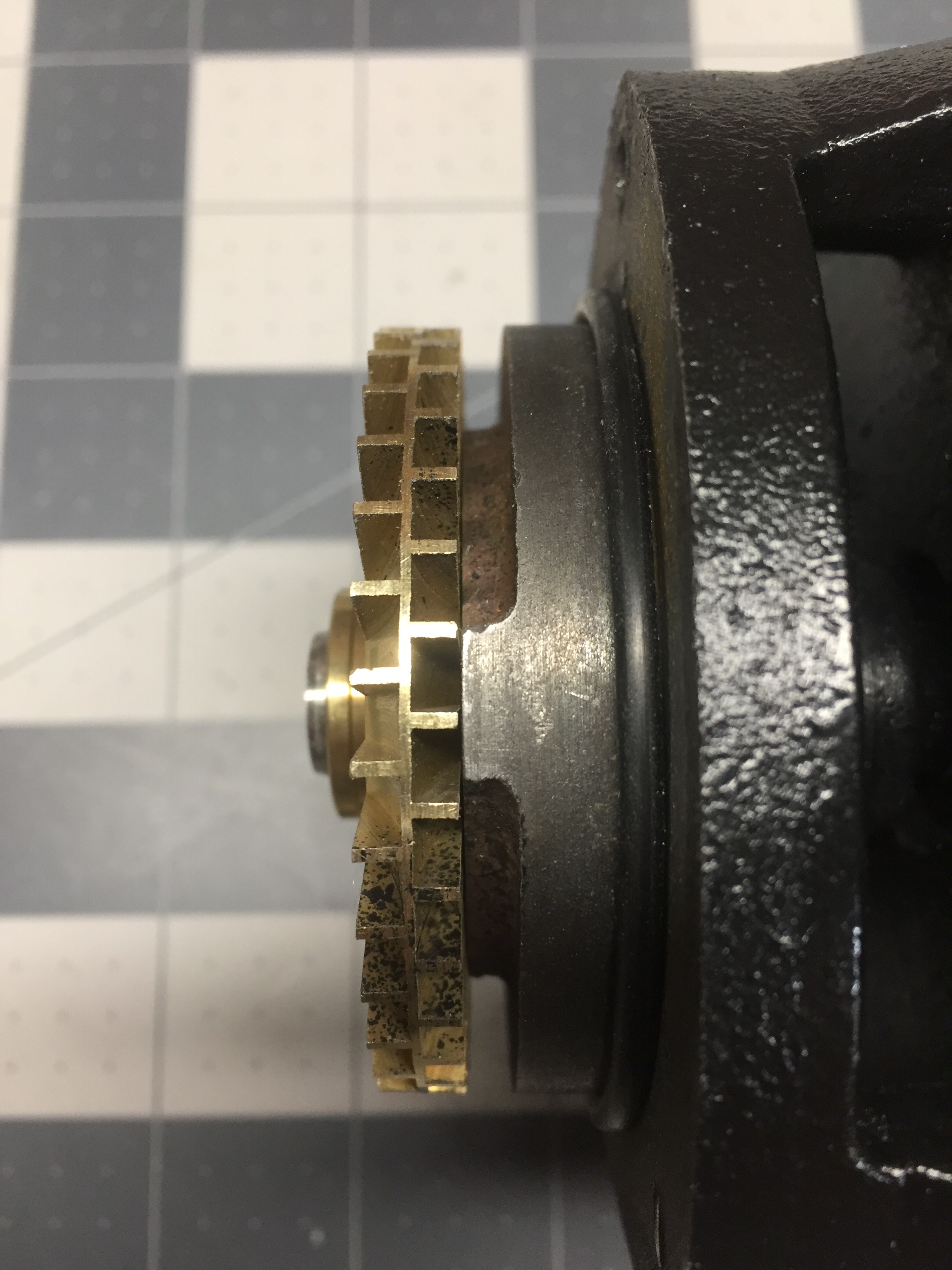
    Above, I have disassembled the casing to get a good look at the impeller which has no forward or backward curvature but rather perpendicular paddles. 

    The impeller doesn't follow the traditional design of a centrifugal pump as the intake is actually routed to the perimeter of the impeller. 

    To my surprise the volute casing of this pump is rather constant and it appears to move water by brute force thus making me believe cavitation will likely be an issue with this impeller design...

    The impeller is sandwiched between two halves of the casing with a cutwater separating the intake from the exhaust. As the water enters the intake it is routed to the volute where impeller is spinning at around 3600RPM. The perpendicular paddles force the water to the outside of the volute as well as imparting some angular momentum into the water. The speed of the impeller and centrifugal flow helps to force the water around the volute casing and up to the cutwater and thus out through the exhaust. 

    It is honestly surprising that this pump is able to generate 60+ psi of pressure. At higher impeller velocities cavitation will most defiantly be an issue. Should offer up an exciting aoitoposy at a later date!  

    Anyways! Carrying on with the teardown.... 

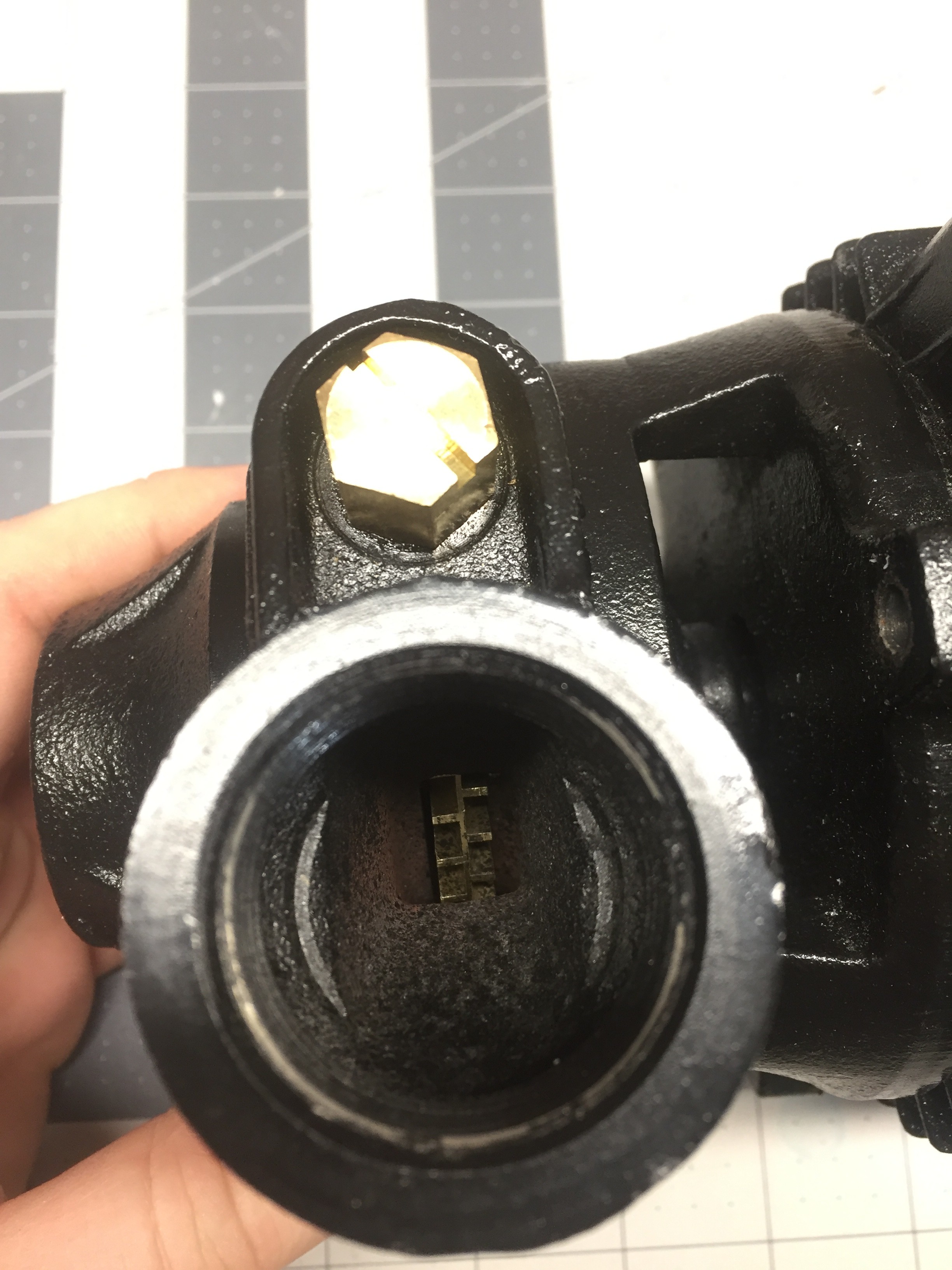
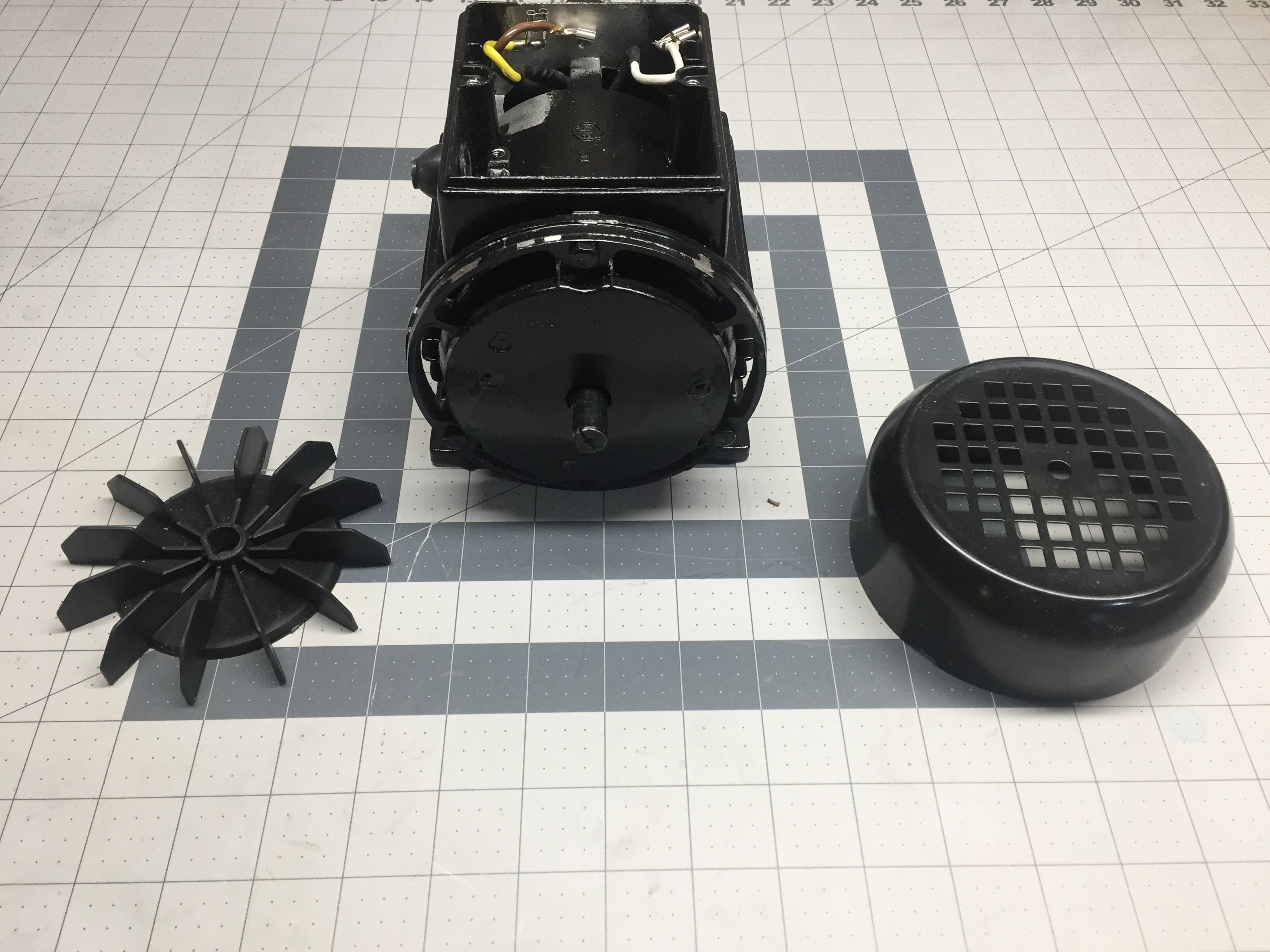
    The fan housing is just friction fitted to the back of the pump... Scratch off the paint and you won't get it to stay in place! 

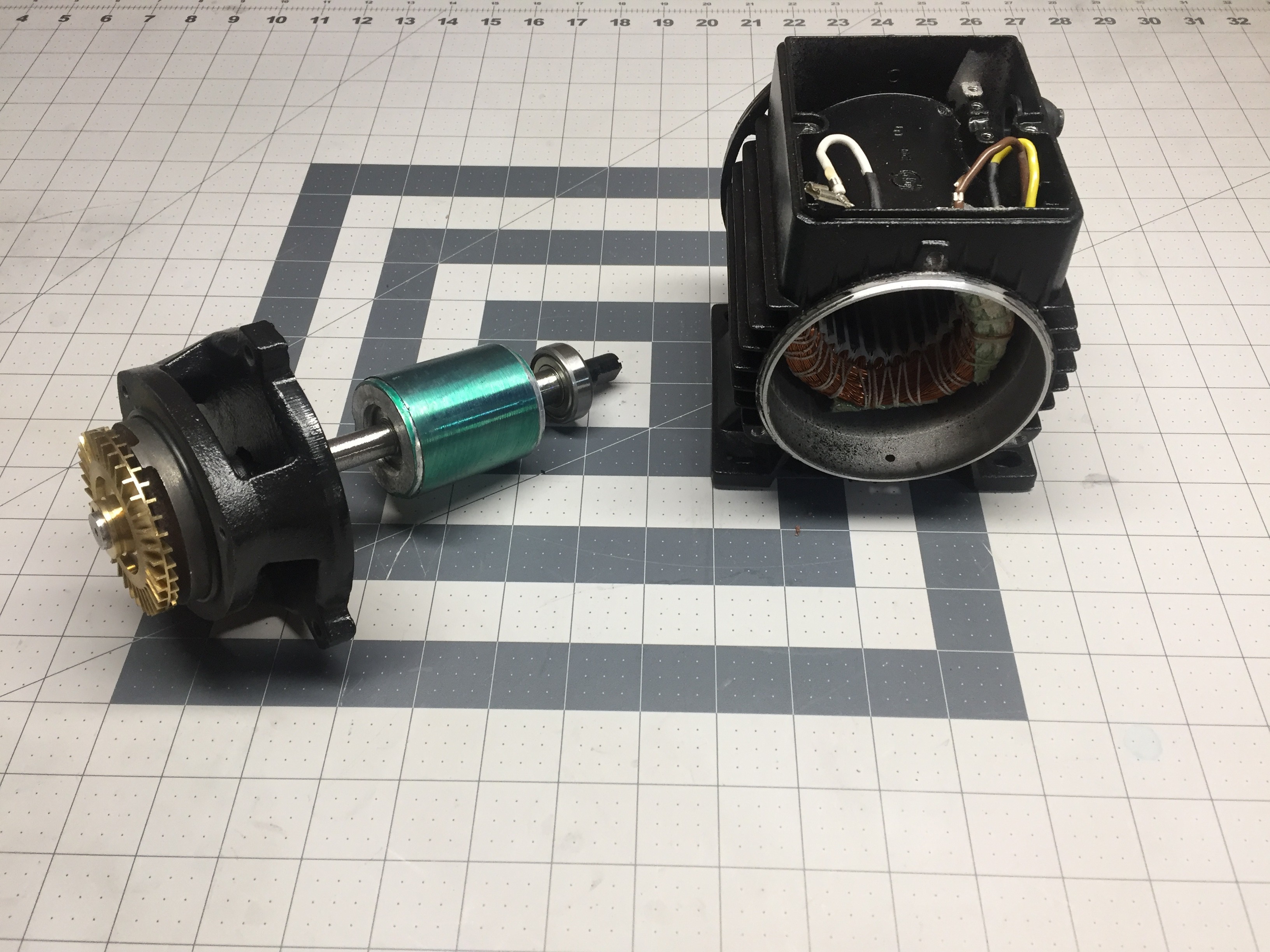
    Lovely motor armature, ready to be cut off and thrown to the side! 

    The plan is to cut the motor armature off and toss it aside along with the stator. I will need to build a new housing to mount the BLDC motor and come up with an adapter to couple the new motor to the shaft of the impeller. This sounds like an excellent job for 3D printing! 

    My motor of choice for this project is a T-Motor U8 - 135KV. I have 4 of them that I picked up good two or three years ago at an online auction for really really cheap. Market price has them around $180 a piece.... Now, hopefully everyone understands why not to build your own variable speed pump! - At least with theses exact parts that is!

    The specs for these motors are pretty good:

    310w maximum continuous power at 48C

    24v to 50v. 

    14A max current at 24v

    So, to match the pumps volumetric output, I will need to get close to 3600RPM which should be around 26v. - Totally doable. 

    A simple 20A controller should suffice but I do have a few 30A ones and a 80A that is programable and communicates with I2C that I may experiment with.  

    In the next log, I will go over the 3D designs and order the prints! 

    Thanks for checking out this project! Hope you enjoyed and will follow along in the next update! 

View all 5 project logs

Enjoy this project?

Share

Discussions

Similar Projects

Does this project spark your interest?

Become a member to follow this project and never miss any updates