 agp.cooper
Sub-Systems! What is that?
This project is the first project for me that has lots of necessary supporting sub-systems. They include:
- The LCD display
- The RTC (Real Time Clock)
- The AT24C32 (EEPROM)
- The rotary push button input device and polling code
- A menu system for:
- Setting the clock to local time
- Setting the local time correction (to Universal Time)
- Setting the LCD LED timeout
- Downloading the data
- Clearing stored data
- Checking the LDR
- Checking the results
- Dealing with power outages (restarting as if nothing happened).
- Setting the time automatically upon recompile.
- Storing the sample data and results.
- Processing the data.
- Displaying the results.
So it is a big deal to coordinate all these systems.
LCD display
The LCD library is very easy to use, the biggest difficulty is selecting the pins to use. Some pins have special functions such as interrupt, PWM, SPI etc. Some other types of display (that use SPI) have fixed pin requirements. The final selection for the pins was designed to be useful for both an LCD display with the typical 4 bit parallel interface, and an SPI type display such as the WaveShare E-Ink display.
For the LCD display:
- EN D7
- RS D8
- D4 D9
- D5 D10
- D6 D11
- D7 D12
- LED D13 (for the display)
For the SPI display:
- Busy D7 (Input)
- Rst D8 (Output)
- DC D9 (Output)
- CS D10 (SS)
- DIn D11 (MOSI)
- ----- D12 (MISO) - Not used
- Clk D13 (SCLK)
As the display is using the D13, I removed both the power and the built in LEDs from the Nano board.
Rotary encoder and push button input
There are different types of rotary encoders and they are not compatible! One type has one transition per detent (the stop position) and the other has two transitions per detent. The first type is the best to use. I am unfortunately using the other type.
Understanding the Rotary Encoder
- When you rotate the encoder clockwise then between detents, Pin A will change state before Pin B.
- When you rotate the encoder anti-clockwise then Pin B will change state before Pin A.
- When both pins have changed state then you have moved from one detent to the next detent (assuming the rotary encoder is of the first type).
- Now all you need to do is flag when both pins have changed state and use the the direction (flag) of the last pin to change state.
Got that? Okay here is the code:
  // Update Encoder Position
  lastPinA=testPinA;             // Save PinA
  lastPinB=testPinB;             // Save PinB
  testPinA=(PIND>>PinA)&1;       // Get PinA
  testPinB=(PIND>>PinB)&1;       // Get PinB

    if (testPinA!=lastPinA) {      // Change in PinA?
      flagPinA=true;               // Flag PinA has changed
      encoderDir=-1;               // Assume it is the last flag to change
    }
    if (testPinB!=lastPinB) {      // Change in PinB?
      flagPinB=true;               // Flag PinB has changed
      encoderDir=1;                // Assume it is the last flag to change
    }
    if (flagPinA&&flagPinB) {      // Both flags have changed
      EncoderPos+=encoderDir;
      flagPinA=false;              // Reset PinA flag
      flagPinB=false;              // Reset PinB flag
    }
(Don't you love the random colours the editor gives to your code!)
Polling or an Interrupt Service Routine (ISR)
There are many option to "connect" the rotary encoder to your code (as above). In my case I used one of the two "unused" interrupt vectors associated with the Timer0 for polling. Basically rather than use an interrupt monitoring a change on the pins, I "poll" the pins using the millis() timer. Timer0 is used for millis(), delay(), micros(), delayMicroseconds(), and PWM output on pins 5 and 6. So providing you don't need to use PWM of pin 5 or Pin 6, you can use the interrupt vectors ISR(TIMER0_COMPB_vect) or ISR(TIMER0_COMPA_vect).
The main reason for polling was that I would have needed three level change interrupts. One for Pin A, one for Pin B and one for the (push button) Switch, and I would still need a timer for debounce of the switch. In the case of polling, these can all be combined into one ISR. Here is the rest of the code:
/* ROTARY ENCODER AND PUSH BUTTON POLLING CODE */
#define PinA 2
#define PinB 3
#define SW   4
volatile bool UpdateSwitch=false;
volatile byte Switch=HIGH;
volatile int EncoderPos=0;
ISR(TIMER0_COMPB_vect) {
  static byte testPinA=(PIND>>PinA)&1;
  static byte testPinB=(PIND>>PinB)&1;
  static byte lastPinA=LOW;
  static byte lastPinB=LOW;
  static bool flagPinA=false;
  static bool flagPinB=false;
  static bool encoderFlag=true;
  static int encoderDir=0;
  static byte testSW=HIGH;
  static byte statusSW=HIGH;
  static byte cntSW=0;

  // Update Encoder Position
  lastPinA=testPinA;             // Save PinA
  lastPinB=testPinB;             // Save PinB
  testPinA=(PIND>>PinA)&1;       // Get PinA
  testPinB=(PIND>>PinB)&1;       // Get PinB

  // This rotary encoder updates twice per detent!
  if ((testPinA==HIGH)&&(testPinB==HIGH)) encoderFlag=true; // Encoder is in detent
  if ((testPinA==LOW)&&(testPinB==LOW)) encoderFlag=false;  // Encoder is between detents
  if (encoderFlag) {                                        // First transition (leaving detent) only
    if (testPinA!=lastPinA) {      // Change in PinA?
      flagPinA=true;               // Flag PinA has changed
      encoderDir=-1;               // Assume it is the last flag to change
    }
    if (testPinB!=lastPinB) {      // Change in PinB?
      flagPinB=true;               // Flag PinB has changed
      encoderDir=1;                // Assume it is the last flag to change
    }
    if (flagPinA&&flagPinB) {      // Both flags have changed
      EncoderPos+=encoderDir;
      flagPinA=false;              // Reset PinA flag
      flagPinB=false;              // Reset PinB flag
    }
  }

  // Update switch with 20 ms debounce
  testSW=(PIND>>SW)&1;
  if (testSW!=statusSW) {
    statusSW=testSW;
    cntSW=20;
  }
  if (cntSW>0) {
    cntSW--;
    if (cntSW==0) {
      Switch=statusSW;
      UpdateSwitch=true;
    }
  }
}
Dealing with two transitions per detent
The code below deals with two transitions per detent by only accepting the one transition per pin. Just comment out these two line if you have a rotary encoder of the first type:
  // This rotary encoder updates twice per detent!
  if ((testPinA==HIGH)&&(testPinB==HIGH)) encoderFlag=true; // Encoder is in detent
  if ((testPinA==LOW)&&(testPinB==LOW)) encoderFlag=false;  // Encoder is between detents
The push button switch
The push button code looks for a change in state and starts a countdown timer. Upon timeout it sets the switch flags:
  // Update switch with 20 ms debounce
  testSW=(PIND>>SW)&1;
  if (testSW!=statusSW) {
    statusSW=testSW;
    cntSW=20;
  }
  if (cntSW>0) {
    cntSW--;
    if (cntSW==0) {
      Switch=statusSW;
      UpdateSwitch=true;
    }
  }
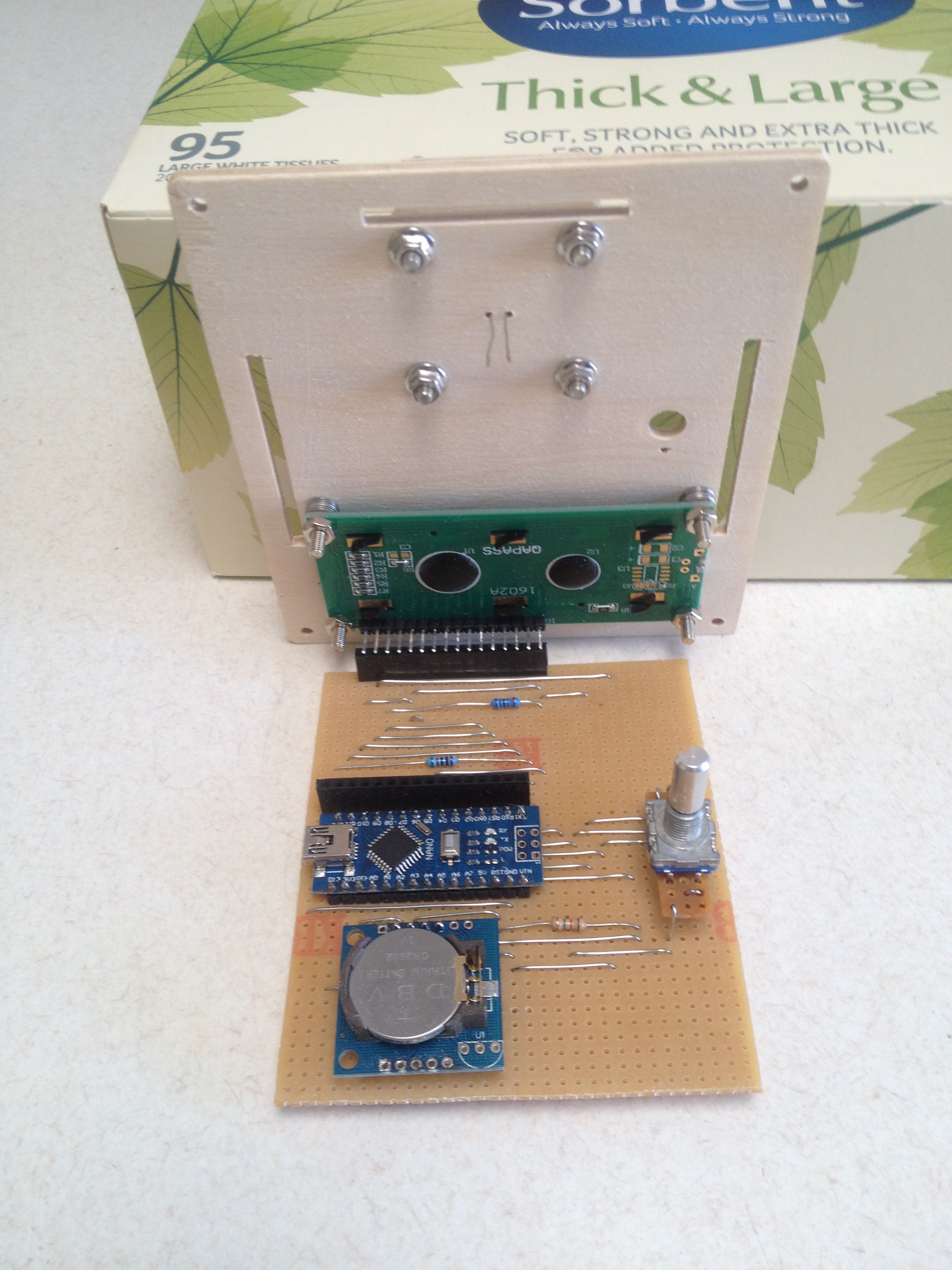
What is inside the box?
I replaced the LDR load resistor so while the box was open, here is a snap shot:
The Menu System
The menu system has been designed to be very simple to update or expand. I have put together a demostration using the rotary encoder to control the blink rate of the builtin LED:
/*
  Rotary Encoder Blink
  ====================
  Written by Alan Cooper (agp.cooper@gmail.com)
  This work is licensed under the
  Creative Commons Attribution - Non Commercial 2.5 License.
  This means you are free to copy and share the code (but not to sell it).
  Also it is good karma to attribute the source of the code.
*/

/*
  ROTARY ENCODER AND PUSH BUTTON POLLING CODE
    Uses Timer0 without upsetting millis(), delay() etc.
    You lose PWM on Arduino/Nano pin 5 (D5).
    Don't turn the encoder too fast as it will not work!
*/
#define PinA 5
#define PinB 4
#define SW   3
volatile bool UpdateSwitch=false;
volatile byte Switch=HIGH;
volatile int EncoderPos=0;
ISR(TIMER0_COMPB_vect) {
  static byte testPinA=(PIND>>PinA)&1;
  static byte testPinB=(PIND>>PinB)&1;
  static byte lastPinA=LOW;
  static byte lastPinB=LOW;
  static bool flagPinA=false;
  static bool flagPinB=false;
  static bool encoderFlag=true;
  static int encoderDir=0;
  static byte testSW=HIGH;
  static byte statusSW=HIGH;
  static byte cntSW=0;

  // Update Encoder Position
  lastPinA=testPinA;             // Save PinA
  lastPinB=testPinB;             // Save PinB
  testPinA=(PIND>>PinA)&1;       // Get PinA
  testPinB=(PIND>>PinB)&1;       // Get PinB

  /* If your encoder jumps in steps of two, uncomment this code */
  // if ((testPinA==HIGH)&&(testPinB==HIGH)) encoderFlag=true; // Encoder is in detent
  // if ((testPinA==LOW)&&(testPinB==LOW)) encoderFlag=false;  // Encoder is between detents

  if (encoderFlag) {             // First transition (leaving detent) only
    if (testPinA!=lastPinA) {    // Change in PinA?
      flagPinA=true;             // Flag PinA has changed
      encoderDir=-1;             // Assume it is the last flag to change
    }
    if (testPinB!=lastPinB) {    // Change in PinB?
      flagPinB=true;             // Flag PinB has changed
      encoderDir=1;              // Assume it is the last flag to change
    }
    if (flagPinA&&flagPinB) {    // Both flags have changed
      EncoderPos+=encoderDir;
      flagPinA=false;            // Reset PinA flag
      flagPinB=false;            // Reset PinB flag
    }
  }

  // Update switch with 10 ms debounce
  testSW=(PIND>>SW)&1;
  if (testSW!=statusSW) {
    encoderFlag=true;            // Reset encoder flag (precaution)
    statusSW=testSW;
    cntSW=10;
  }
  if (cntSW>0) {
    cntSW--;
    if (cntSW==0) {
      Switch=statusSW;
      UpdateSwitch=true;
    }
  }
}


/* MENU SET UP */
enum NoYes {N,Y,A};
enum MenuLevel {Top,Menu,Set};
enum MenuItem       { Exit_Menu  , Delay_MS  };
char* menuName[]   ={"Exit Menu ","Delay ms "};
char menuNumeric[] ={         N  ,        Y  };
int menuValue[]    ={         Y  ,      500  };
int menuValueMin[] ={         N  ,       10  };
int menuValueMax[] ={         Y  ,    32750  };
int menuValueStep[]={         Y  ,       10  };
int menuSize=sizeof(menuName)/sizeof(char*);
int menuLevel=Menu;

// Our variable to set the delay period
unsigned long intervalMillis=1000;

bool processMenu(void) {
  static int lastPos=Exit_Menu;
  static int lastMenuLevel=Top;

  // Disable polling
  TIMSK0&=~(1<<OCIE0B);

  // Pre-empt menu level display
  if (menuLevel!=lastMenuLevel) {
    lastMenuLevel=menuLevel;
    if (menuLevel==Menu) {
      Serial.print("Menu: ");
      Serial.print(menuName[EncoderPos]);
      if (menuNumeric[EncoderPos]==Y) {
        Serial.println(menuValue[EncoderPos]);
      } else {
        if (menuValue[EncoderPos]==N) {
          Serial.println("N");
        } else {
          Serial.println("Y");
        }
      }
    } else if (menuLevel==Set) {
      Serial.print("Set:  ");
      Serial.print(menuName[lastPos]);
      if (menuNumeric[lastPos]==Y) {
        Serial.println(menuValue[lastPos]);
      } else {
        if (menuValue[lastPos]==N) {
          Serial.println("N");
        } else {
          Serial.println("Y");
        }
      }
    }
  }

  // If push button pushed toggle menu level
  if (UpdateSwitch) {
    UpdateSwitch=false;
    if (Switch==LOW) {
      // Re-enter menu if button pushed (for long enough)
      if (menuLevel==Top) {
        menuLevel=Menu;
        lastMenuLevel=Top;
        lastPos=Exit_Menu;
        EncoderPos=Exit_Menu;
        menuValue[Exit_Menu]=Y;
      } else {
        // Toggle menu level
        if (menuLevel==Menu) {
          menuLevel=Set;
        } else {
          menuLevel=Menu;
        }
        if (menuLevel==Menu) {
          // Restore item menu position
          EncoderPos=lastPos;

          /* Exit menu if done! */
          if ((EncoderPos==Exit_Menu)&&(menuValue[Exit_Menu]==Y)) {
            menuLevel=Top;
            // Set the delay
            intervalMillis=menuValue[Delay_MS];
            Serial.println("Menu Exited!");
          }

        } else {
          // Set value for edit menu
          EncoderPos=menuValue[lastPos];
        }
      }
    }
  }

  // If encoder turned
  if (menuLevel==Menu) { // Select menu item
    if (lastPos!=EncoderPos) {
      if (EncoderPos>=menuSize) EncoderPos=0;
      if (EncoderPos<0) EncoderPos=menuSize-1;
      lastPos=EncoderPos;
      Serial.print("Menu: ");
      Serial.print(menuName[lastPos]);
      if (menuNumeric[lastPos]==Y) {
        Serial.println(menuValue[lastPos]);
      } else {
        if (menuValue[lastPos]==N) {
          Serial.println("N");
        } else {
          Serial.println("Y");
        }
      }

    }
  } else if (menuLevel==Set) { // Set/edit menu item value
    if (menuValue[lastPos]!=EncoderPos) {
      if (EncoderPos>menuValue[lastPos]) {
        EncoderPos=EncoderPos+menuValueStep[lastPos]-1;
      } else {
        EncoderPos=EncoderPos-menuValueStep[lastPos]+1;
      }
      if (EncoderPos>menuValueMax[lastPos]) EncoderPos=menuValueMin[lastPos];
      if (EncoderPos<menuValueMin[lastPos]) EncoderPos=menuValueMax[lastPos];
      menuValue[lastPos]=EncoderPos;
      Serial.print("Set:  ");
      Serial.print(menuName[lastPos]);
      if (menuNumeric[lastPos]==Y) {
        Serial.println(menuValue[lastPos]);
      } else {
        if (menuValue[lastPos]==N) {
          Serial.println("N");
        } else {
          Serial.println("Y");
        }
      }

    }
  }
  // Enable polling
  TIMSK0|=(1<<OCIE0B);

  return (menuLevel!=Top); // Return true if menu active
}

void setup() {
  // Setup for Keyes rotary encoder and push button
  pinMode(5,INPUT_PULLUP); // Rotary PinA or Clk
  pinMode(4,INPUT_PULLUP); // Rotary PinB or DT
  pinMode(3,INPUT_PULLUP); // Rotary SW
  pinMode(2,OUTPUT);       // Power for onboard pullup resistors
  digitalWrite(2,HIGH);    // Turn on power

  // Set up Blink
  pinMode(LED_BUILTIN,OUTPUT);

  // Turn on polling ISR
  OCR0B=0xA0;
  TIMSK0|=(1<<OCIE0B);

  // Initialise Serial
  Serial.begin(9600); // Stardard serial speed
  while (!Serial);    // Wait for the Serial system to come up

  // Print welcome messeage
  Serial.println("Rotary Blink");
  Serial.println("Hints:");
  Serial.println("  1 Turn the encoder to navigate the menu");
  Serial.println("  2 Push the button to change the setting");
  Serial.println("  3 Turn the encoder to change the setting");
  Serial.println("  4 Don't turn the the encoder too fast!");
  Serial.println("  5 Push the button to save the setting (i.e. Y)");
  Serial.println();
  Serial.println("  6 Select 'Exit Menu'");
  Serial.println("  7 Push the button to change the setting");
  Serial.println("  8 Push the button to save the setting");
  Serial.println("  9 You should have exited the menu and Blink is now running");
  Serial.println();
  Serial.println("  10 Push the button to re-enter the menu after 'Exit Menu'");
  Serial.println();
}

void loop() {
  static unsigned long previousMillis=0;
  unsigned long currentMillis;

  if (!processMenu()) {
    /* Run this when not in menu */

    // Blink without delay (intervalMillis is set by the rotary encoder)
    currentMillis=millis();
    if (currentMillis-previousMillis>=intervalMillis) {
      previousMillis=currentMillis;
      digitalWrite(LED_BUILTIN,!digitalRead(LED_BUILTIN));
    }
  }
}
Okay, its a bit long but it has:
- Polling for the push button rotary encoder
- A menu system (you can set the blink rate)
A nice feature is that the delay increments/decrements in steps of 10 (programmanble).
Discussions
Become a Hackaday.io Member
Create an account to leave a comment. Already have an account? Log In.