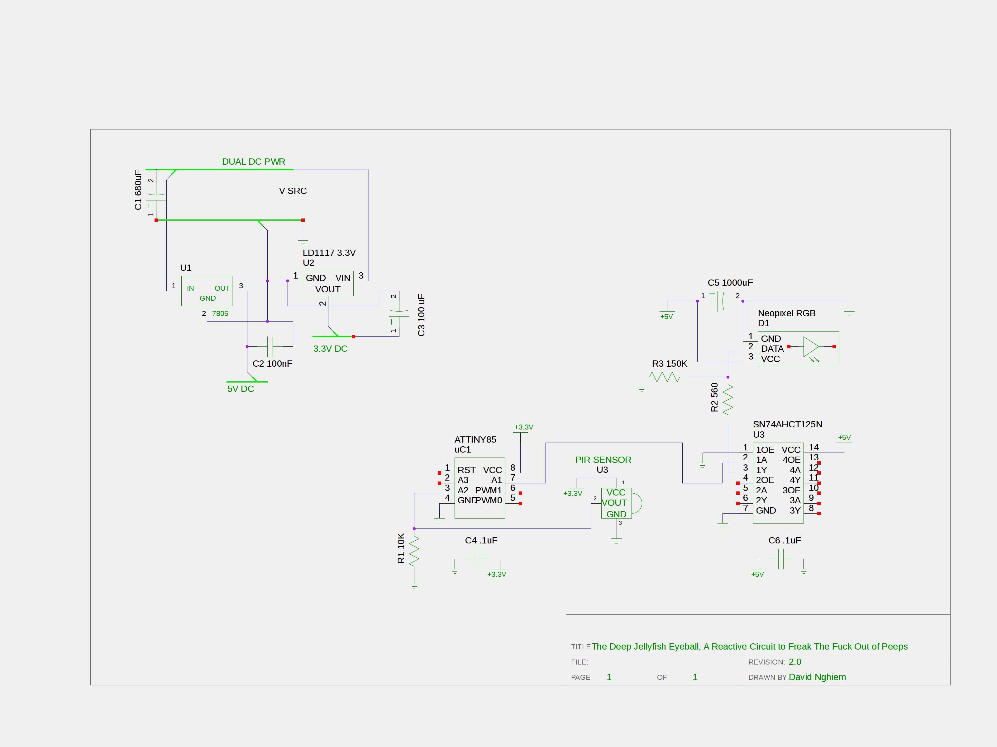
This is the initial circuit diagram for one of the sensor nodes. It's going to get expanded into a sort of hybrid digital/neural circuit emulator design, using a synapse discharge as the main model. The entire Jellyfish will have about 11 microcontrollers, right now, they're independent of each other. In the future, or near future provided we have time, they'll be networked with each other in a mix of analog circuitry that simulates a neural synapse, using the high output of a digital circuit as a discharge signal, and that interfaces with digital circuitry. I call it the "Wannabe Jellyfish Cyborg."

This is just the first sensor node which controls the RGB LED strips.
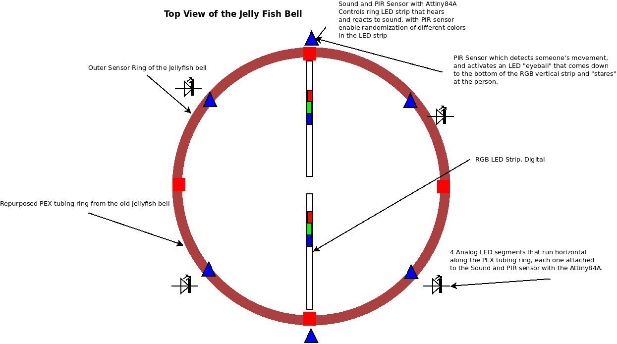
This is the overall diagram of the concept.

Obviously, because the signalling is going to be digital, there aren't going to be any weights. The only thing that can be weighted is from the sound sensors, and that we're not going to use for the time being. I know, some of you are probably asking, "then what's the point?" There is no point other than to create a signal that fires off in analog at various points around the bell creating... ART!
And, here's the basic code.
The Deep Combjelly Simulation Code
 Casual Cyborg
Discussions
Become a Hackaday.io Member
Create an account to leave a comment. Already have an account? Log In.