Matt
Matt-
Stickvise and ESPLux Boards
06/17/2015 at 09:47 • 0 commentsHi All! Sorry for the severe lack of updates. This past week work has been insane. I have had bits and pieces arriving at home, and have had no time at all to play with them all. Shame.
The first thing to turn up was my ESPLux boards! They are looking like they should do the business. I've put a multimeter across them and everything seems to look ok. There are a few things that I will look at changing in the next board revision;
- First up is the through hole parts. As I said in my video below, I didn't realise the extra cost involved in placing through hole parts, not that this is my intention in the first instance, but potentially in the future if anyone other than myself is interested in it!
- Silkscreen. I kinda bummed out on this, I should have labelled things on the top side of the board a bit better. Never mind!
- The via on the top left of the board, near the rectifier for some reason is much bigger than I'd anticipated. I'm assuming one of my design rules is broken in KiCad. I'll have to look into that.
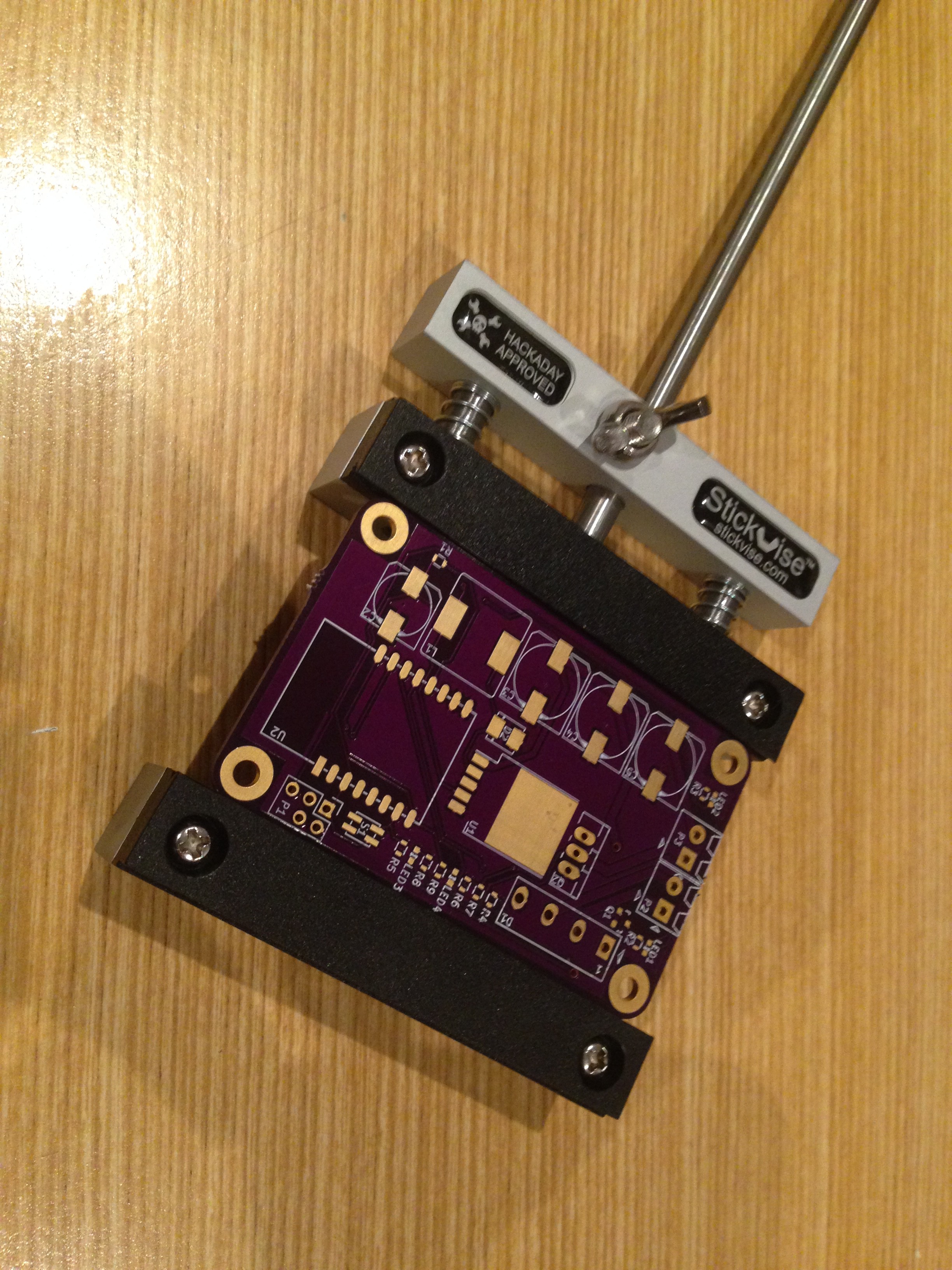
Next thing to turn up was my stickvise! Thanks Hackaday for this, I really appreciate it! It is really well made. It has a great amount of pressure on the board, its hefty enough to not slide around my desk, and you can stand it on its side to get to both sides of the board.
Here is a photo of the ESPLux board in my stickvise:
![]()
Hopefully I can have the board assembled on Monday evening. I'm not progressing quick enough for my liking!
Also, just a shoutout to all those people who are following my project. I really appreciate your support. Just seeing that number there helps keep my motivation level up.
-
Block diagram
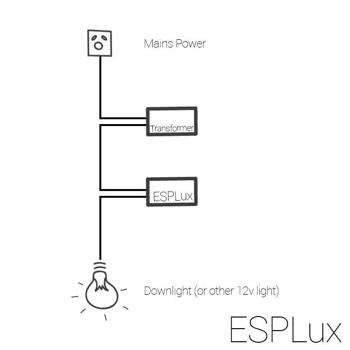
06/08/2015 at 13:01 • 0 commentsHere's a quick drawing for you. It shows how the ESPLux would be connected to a downlight.
![]()
Of course, the input can be a standard 12-24v power supply (both AC or DC), and the light could be any type of LED or incandescent globe. I've tested up to about 20w with no issues. 30w and the rectifier starts getting a bit too warm for my liking. I've found some parts on http://parts.io that I can replace the rectifier with, that'll be my next task after getting this batch of boards back.
-
Overview Video
06/04/2015 at 05:39 • 0 commentsHowdy!
I've uploaded a new video! It is a bit of an overview of where I am at with the project so far. My thought was for this to be my first video for the quarter finals, but it is too long. I'll end up either trimming this video down, or making a new one for that submission.
Please excuse my crappy GoPro. It is the best camera I have, and it's quite noisy (both in way of video and audio). If all goes well with this next board that turns up, my plan is to go in the running for Best Product. It is a bit humbling looking at all the other products out there, I feel as though my little project doesn't hold a candle to the others that I have seen. I don't expect it to go far, but I might as well give it the best shot possible. Having said that, this has all been a great learning exercise for me so far. This is both the first time that I have made any videos, or any real boards beyond messing around, and I am really enjoying the experience. Thanks HAD for giving me the push I needed to get my little project underway. You have already given me more than I ever expected to win. Thanks for the prizes I have won so far, I know they will all come in handy.
-
Fail
06/04/2015 at 04:58 • 0 commentsI just got an email from OSHPark saying that my ESPLux board has been posted! Yay! I promptly realised that I haven't ordered the stencil for it. Boo. Looks like I will be hand soldering the first one ...
-
ESPProgrammer
05/28/2015 at 13:05 • 0 commentsHowdy!
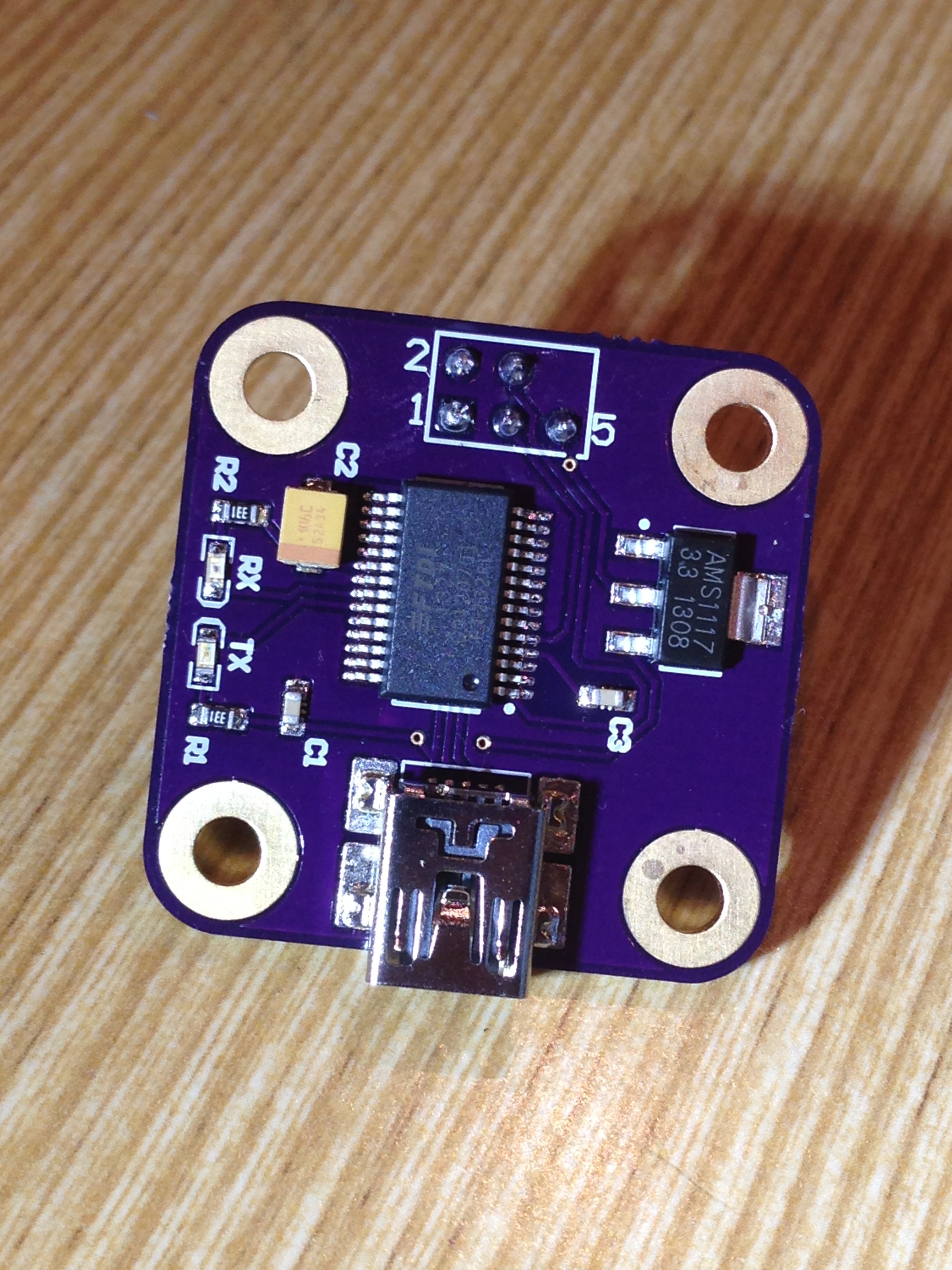
I have a new board completed! This my first USB enabled device I've made, a programmer for the ESPLux. Really, it is just an FTDI chip with a 3.3v regulator on board, with a pinout that suits the ESPLux programming header. I think I need to play around with the location of the temperature probe in my reflow oven, I don't think the board quite got hot enough .. I'm still learning this reflow soldering thing.
Here is a photo:
![]()
It looks like my beginners luck is slowly running out. There are two mistakes on this board. First, I forgot to check for airwires before sending the board off (fail) and missed that one of C3's pads doesn't actually go to ground. I placed a copper pour over the whole board, and up until this board, and the ESPLux board, it has covered every pin that I need. Lesson learnt! Copper pours aren't a magic routing bullet!
The second mistake was that the holes I put in for my pogo pins aren't big enough. I knew this, and it completely slipped my mind. I just wanted to use up some of my OSHPark credit!
In any case, C3 seems to not be a requirement for the board working, it just looks like a filtering cap. Worst case, I'll chuck in a bodge wire to get it working.
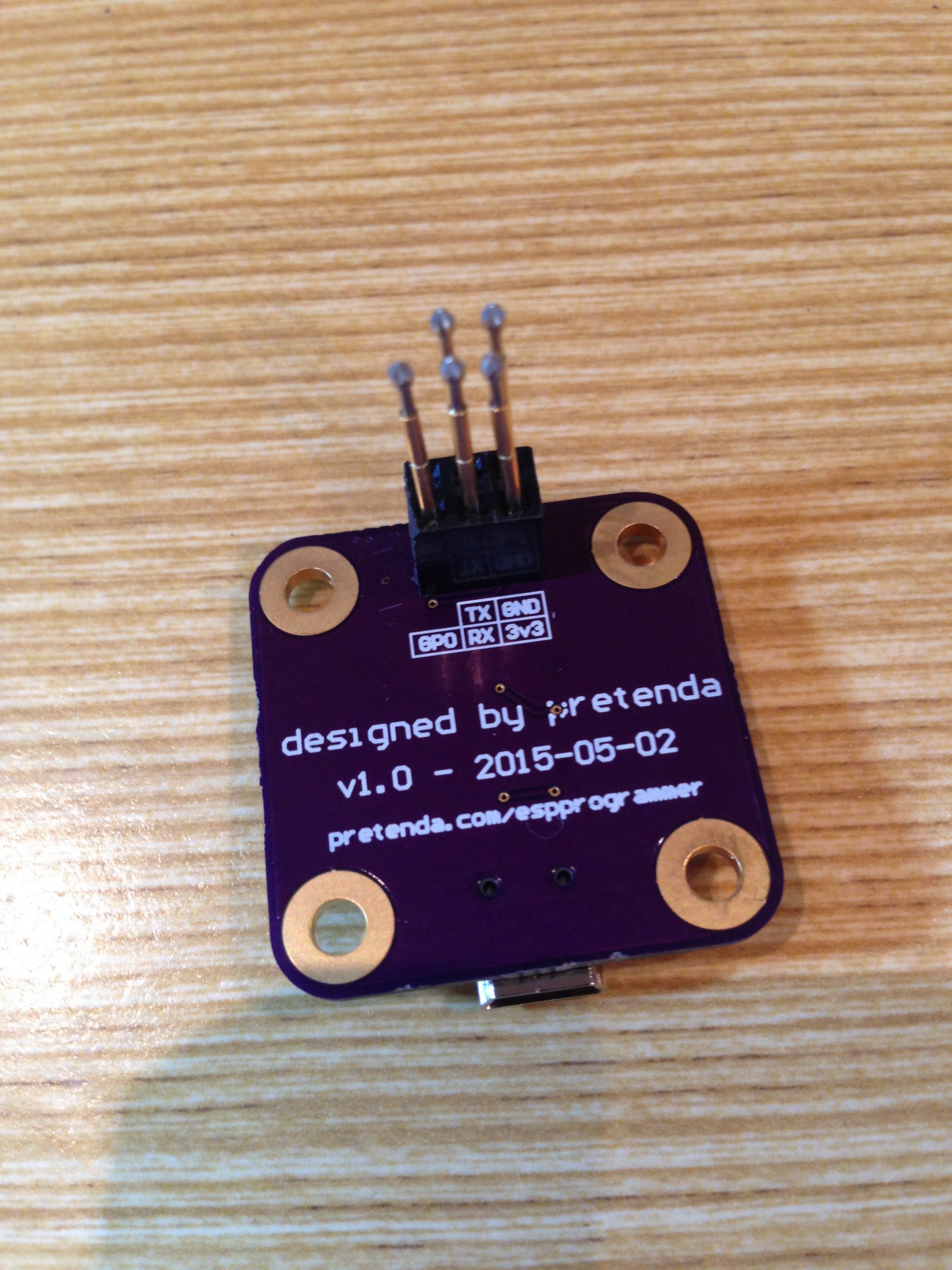
The fail with the pogo pins has kind of turned out in my favour. Here's what I did (sorry for the poor focus, my phone doesn't like doing macro shots):
![]()
I ended up mounting a 2.54mm female header block on the board, and then drilled out the holes in the plastic to 1mm. This lets me fit the pogos into the header block, and an added bonus is I can pull the pogos out, and use it as a standard 2.54mm header. This means for my first ESPLux, I can use the same boards, solder in a 2.54mm male header and work without having to hold the pogos in place.
I thought I should go through a little bit of background on the pinout for you. I have explained this before, but I may as well explain it here alongside the pictures of the finalised board. Pins 1-4 are pretty simple. It includes ground, 3v3, TX and RX. The 5th pin is where (hopefully) things get a little bit more exciting. On the ESP8266, for normal operation, you need to pull GPIO0 high (in other words, join it to 3.3v). To program it, you need to pull it low (or join the pin to ground). On the ESPLux board, I have put a 10k resistor between GPIO0 and 3.3v, and then ran a trace for GPIO0 up to the programming header. On the ESPProgrammer, the 5th pin is connected directly to ground. This means when the programmer is connected, GPIO0's path of least resistance is to ground, which puts the ESP8266 into programming mode when the header is connected. In hindsight, I probably should have put a jumper on the top of the board so I can easily enable to disable this feature, but in the grand scheme of things, it probably won't impact me that much. I can always pull out the pogo if it becomes an issue.
In any case, the ftdi chip works! I have yet to see if the functionality I described above works, but when I get the boards from OSHPark I give it a shot.
Edit: This also means I can now start working on my firmware again! Here's hoping for an update on that soon.
-
First revision of ESPLux board
05/21/2015 at 03:11 • 0 commentsHi everyone!
I've been hard at work designing up the PCB for ESPLux! I have sent the first revision off to OSHPark for fab, hopefully I haven't missed anything. I am really glad that I made the breakout boards in the first place, they made creating the board schematic much much easier. I have built it up in Kicad, the sources for the board are all over on the ESPLux GitHub page. This was the first time I have used Kicad, it took a short while to get my head around, but hey, I think everything has turned out just fine. I watched a bunch of the Contextual Electronics courses, which helped explain it all quite a lot! Thanks Chris Gammell! I thought that I would have a play around with the BMP to silkscreen option, looks kinda neat!
Hopefully I have enough room around everything for heat dissipation. I have put the rectifier close to the edge of the case, hopefully I can get a heatsink that makes up part of the side of the case.
I have most of the parts in my parts bins, I will probably have to look at buying some more ESP's soon, and I only have one switchmode regulator left, so I'll need to grab some more of them.
While I am waiting for everything to turn up, I think I will start working on the web pages that you can switch the lights on and off from. I still haven't got a 3.3v FTDI cable available, and I am not super keen to use my 5v one, despite people saying that it works just fine.
Here is a render of the board:
![]()
![]()
-
Heat!
05/20/2015 at 00:29 • 0 commentsHi everyone,
My life has been a bit busy recently, and so I havent had much of an opportunity to work on ESPLux. One thing that I have been doing is sourcing various LEDs from people so that I can test out my circuits with a wide variety of light sources. The thing that I have been noticing is the rectifier gets quite hot after a while. I wasn't really expecting this, although I probably should have. When it comes to designing my case, I am thinking I should probably incorporate some sort of heatsink into the design to try and wick away some of that heat.
Anyway, I am slowly working away at the first single board prototype. From what I can see, I should be able to fit it into the 70x43 (DP7043) Sick of Beige footprint, which is slightly smaller than a credit card. We will just have to see about that heat.
Hopefully will post another update soon!
-
Today isn't my day
05/13/2015 at 06:57 • 0 commentsWell, today I learnt a lesson. Watch where you shove your scope probes. Thank goodness I didn't do any more damage than I did. This is my best explanation for what happened to me. Feel free to correct me if I am wrong, I'm keen to learn about my mistakes!
I've been probing the output of the MOSFET now for quite a while, watching the waveform that is being created, it looks pretty. I haven't had my FTDI board plugged in now for a while, I haven't done any firmware updates or anything for quite some time. In any case, I thought that I should plug it in and upload a new lua script to play around with tcp and the like. Turns out this was a really bad idea.
I've watched the video by Dave Jones from the EEVBlog titled How NOT to blow up your oscilloscope a while back, I probably should have paid a little more attention! Turns out I made a rookie mistake. I had made sure that my power supply was isolated. There is no ground pin on the cable, and i probed it just to make sure. This meant to me that I could probe around the board as much as I liked! That is, until I plugged my USB cable in. Fail. When I plugged it in, I heard a pop, then Windows making a noise telling me that my USB device had disconnected. Turns out I've shagged both my ESP8266 and my FTDI Breakout board. The ESP8266 gets nice and toasty really quickly when I have 3.3v plugged into it, and the blue light stays on. The FTDI breakout just isnt even recognised anymore.
I'm a bit annoyed with myself, I should have known better. I even checked the power supply to make sure I was alright, the USB cables ground didn't even cross my mind. You live and learn. I have another FTDI breakout on the way now, and I've soldered up a new ESP8266 breakout. An expensive (both time and money) mistake, but it could have been much worse.
On another note, before i screwed everything, I made up this video. I'm still not used to hearing my own voice. Sorry for sending everyone to sleep ;)
It goes through what the waveform look like connected to a typical 12v iron core transformer. It isn't as good as I was hoping, but it should be enough. Any LED light worth its weight will have additional smoothing capacitors built in to be able to cope with the small voltage drop. I'm thinking it might be worth my while adding an additional footprint for an extra capacitor on my first prototype just in case.
It might be a while before I can post any meaningful updates now that I've done this, I need to wait for the slow boat to arrive here in Australia with my FTDI breakout on it. I guess I'll start working on putting all this together on a prototype board.
I've also been meaning to post up a new picture of my setup. I cut a piece of clear perspex to mount each of the boards on, I got a bit sick of them floating around my desk. So here it is (original):
![]()
-
Solder paste
05/12/2015 at 13:00 • 0 commentshi again!
Another short update. I've been playing around with the setup a bit more. Things seem to be doing relatively well. I'm running off a 12v iron core transformer now, testing the voltage after the rectifier and the capacitor seems to be looking ok. I could do with a bit more capacitance I think though, my output voltage isn't quite as smooth as I would have liked. Even with this though, the regulator copes perfectly fine, and outputs a beautiful 3.3v. I do have one problem at the moment that I don't understand. For some reason when I am running off the AC transformer, with a pwmed output, every so often my voltage goes negative when it should be 0v. I'm not quite sure what I am doing wrong, if anything. It doesn't seem to effect the output, but it's something I need to look into further. If you know what's happening, please let me know. Edit - Well, that was simple, I just didn't have a big enough load on it. Once you put the light on it, the signal smooths right out.
Anyway the reason for the post is that I've uploaded a video to YouTube on my first solder paste experience.
As you can see, I'm not so confident on camera :) apologies for the quality of the video, it is my first ever video I have recorded that amounts to anything.
In the end, before I put my regulator on, I put a bit more solder paste on. This is probably what caused it to twist around a bit, as you can see from the last four seconds of video.
Anyway, onwards and upwards. Things are looking good. I think I need to slap on a few more caps to smooth out my voltages a bit more, and probably add an additional cap specifically for the regulator to make sure it gets clean power.
Also as I mentioned in my comment to Robert below, I'm looking to implement openHAB support for this project. It seems to be the go-to home automation system out there. I'm in the process of setting it up for my place at the moment.
-
Plodding along
05/08/2015 at 11:09 • 0 commentsHi everyone!
I thought I'd post a quick update as to where I'm at.
First up, I'd like to say another big thank you to hackaday for choosing my project to win a LightBlue Bean! I'm keen to get my hands on this and have a play around, see what it is capable of!
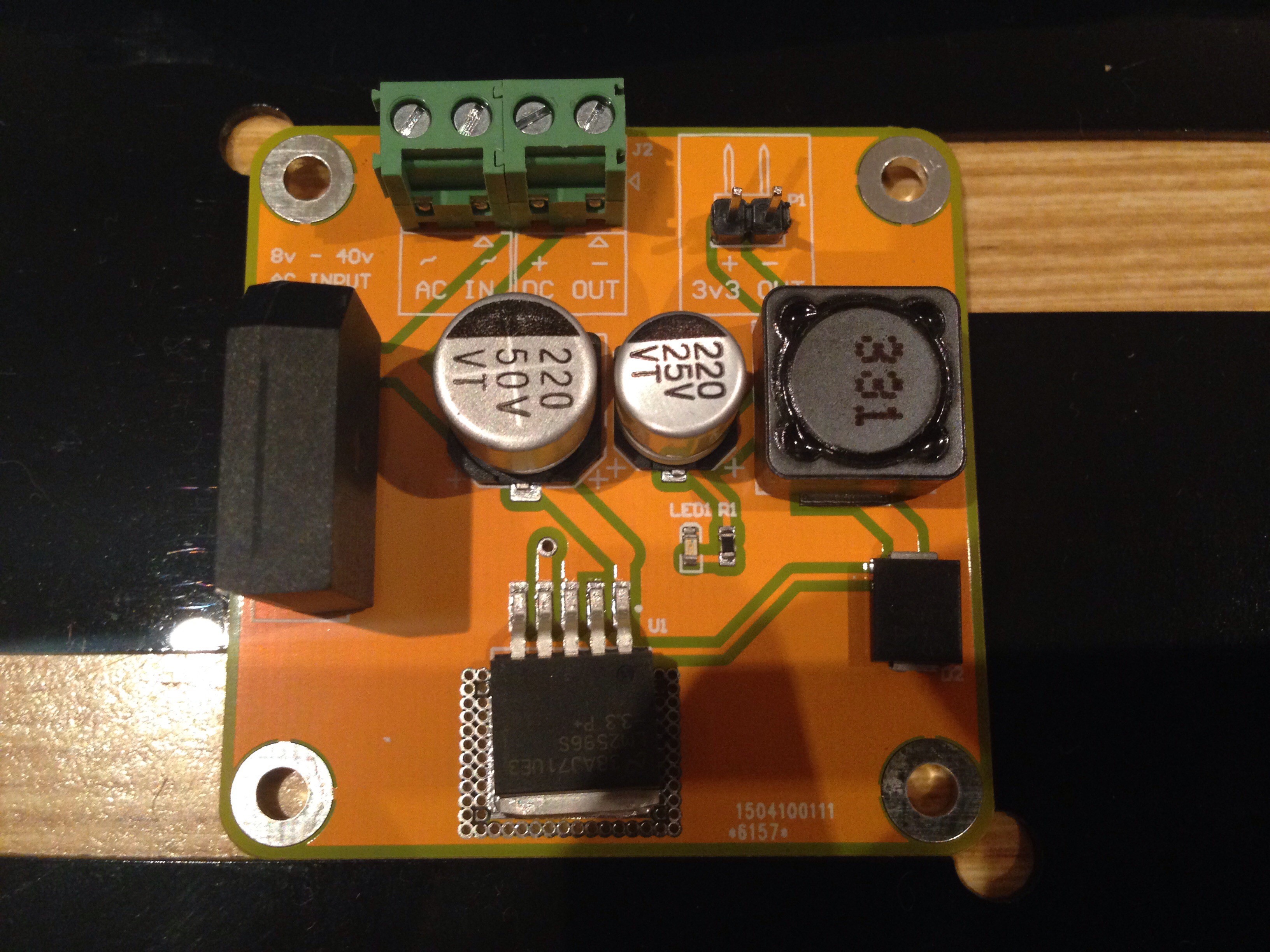
The board I have had the least confidence in has been the power supply board. I feel a little out of my league with it, but have given it a shot in any case. The boards arrived a few days ago, and up until last night I hadn't had an opportunity to play with them. Now I have! I think all the time pouring over the schematics for the board paid off, so far everything seems to work a treat. I've powered it off my lab power supply, which drops down the 3.3v line beautifully. The filtering cap and bridge rectifier work well, although I haven't put it under load yet. In any case, the base schematic looks like it is fine, just the values of some of the components might need to change depending on the performance of it under load.
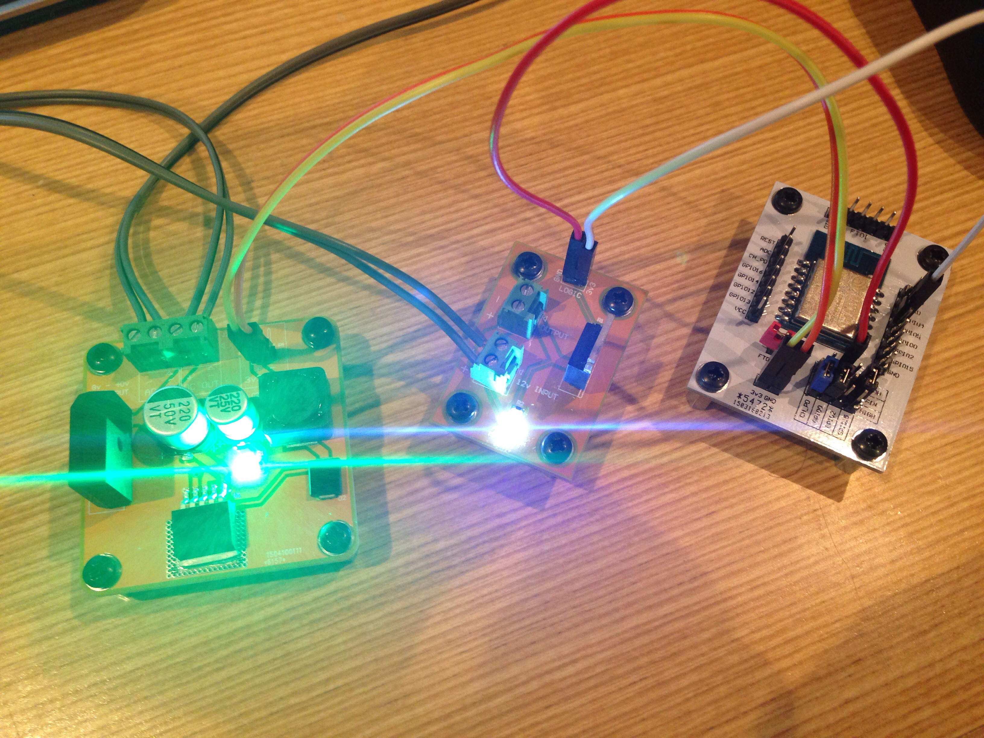
As you can see in the photo below, things are looking fairly positive. The green light on the power supply board is being powered from the 3.3v rail. The esp breakout on the right is being powered from this rail, and is switching the MOSFET on in the centre board, turning on the white LED which is being powered from the raw (12v) dc output of the power supply.
![]()
My next test will be to power it from an iron core transformer like I anticipate it using in the real world, and throw a downlight on it to see how the voltage output turns out with a bit more of a load on it.
One other thing I thought I'd have a play around with was solder paste and using a stencil. Some of the parts, like the caps and inductor, were looking like they would be a bit of a challenge to hand solder. When everything turned up, I think I was right. I bought a stencil from OSHStencils.com. They provide an awesome service. Thanks guys! The stencil arrived before pretty much anything else did. Overall, the end result turned out pretty great if I do say so myself. I've made up a video of my first ever solder paste application, I just need to edit it and post it up on YouTube. I'll post an update when I get around to it. This weekend is pretty busy for me, so hopefully my testing and editing can be done throughout the week.
Unfortunately I haven't had a great deal of time to work on the firmware. I haven't forgotten, I will post it up when I have something that is semi respectable.
![]()
ESPLux - Smarts for your downlights
A circuit you can place inline with your existing low voltage lights to allow for wireless control