Matt
Matt-
Double Oops!
05/04/2015 at 11:15 • 0 commentsDon't look, my noobness is showing!
I just got my switching breakout boards! It seems as though, however, I read the wrong webpages. I read that I don't really need a pulldown resistor for this kind of MOSFET. Seems as though I should have trusted my gut and thrown one in. Not to worry, I soldered a little 0603 resistor between the two logic pins and that did the trick. Ideally I think it should probably be between R1 and the MOSFET, but this is life. I will update the board soon with the appropriate changes in case anyone wants to use it for some reason.
My second oops was similarly small, this time I don't have an internet to blame. I put my LED footprint in back to front. After two or three lost tiny little LEDs, I resoldered one in the correct polarity and it all works! Hooray!
I guess also this is the point of making up these separate boards, it helps weed out these problems before they get hidden in a bigger board. I know all you EE's out there are pointing and laughing at how small each of my demo boards are, but it is all a learning process for me.
One other thing that caught me a bit off guard, looks like my proto-pack got me more than i bargained for, I ended up with 22 copies of this board. Kinda slightly overkill for me, but hey, at least I have some spares.
Hopefully my power supply board turns up by the end of the week. It was shipped 3 days after the previous lot, so it shouldn't be too far away.
I'm getting a bit sick of boards floating around my desk. I think I'll cut up a bit of perspex or something to mount them all onto. A project for another day I'm afraid.
Here's the board in any case! (I probably should have waited until after I was off the phone so i had an extra hand to hold those screw terminals in place so they were straight... oh well)
![]()
Heres the setup so far, with the light dimmed (my camera is pretty terrible - sorry)
![]()
And here is my pulldown resistor bodge
![]()
Heres the album if you want to see more.
-
Programmer
05/02/2015 at 10:57 • 0 commentsLooks like my boards aren't here for the weekend. Oh well. Thanks to Hackaday for the OSHPark voucher, really appreciate it. While I'm waiting, I've made another small board up. I'm starting to get quite a collection on my desk. I've decided to build up a specific programmer for my ESP boards I'm making. There isn't really any reason for it other than for a bit of fun. Hopefully though it does make life a bit easier in the future if I am programming a bunch of them at once. It has a discreet voltage regulator unlike the sparkfun FTDI Basic board, which means no need for an external power supply anymore (hooray!). I've also broken out GPIO0 on the header, which means i can put a 10k pullup resistor on that pin on the main board, then when i put the programmer on it, it pulls it to ground. It should work i think! I was thinking of using a non standard header size, but i think in the end it'll just cause me more grief than it's worth.
Anyway, here it is.
![]()
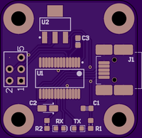
It is based off the DP3030 Sick of Beige board size. It uses an FTDI FT232RL USB-UART IC for its brains, and has an LM1117 3.3v voltage regulator to be able to provide the appropriate amount of power to the ESP8266. Using the voltage regulator in the FTDI chip itself is not a great idea. I've used a 6 pin 2.54mm header and dropped pin 6 out of it. This gives it some polarity so I can't accidentally plug it in the wrong way. I know a whole bunch of people are super keen on Micro USB connectors, but for some reason or other, most of the USB cables I have floating around here are Mini USB, and so that's what I've stuck with here.
Here is a link to the board on OSHPark.
Here is a list of parts required:
U1: FTDI FT232RL SSOP (Be weary of counterfeit chips! Dave Jones says so!)
U2: LM1117 3.3v SOT223
R1, R2: 330R 0603 resistor or there abouts
RX, TX: 0603 LEDs
C1, C3: 100nF 0603 ceramic cap
C2: 4.7uF 3216 Tantalum cap
J1: Mini USB connector
(Unlisted): 3x2 2.54mm header with one of the corner pins ripped out.
As with all my other boards, this is untested so far. I will update this post when I know it works/doesn't work.
-
OSHPark!
04/30/2015 at 23:20 • 0 commentsHey everyone, I just wanted to say a big thank you to Hackaday and OSHPark for the $50 PCB fab voucher! Congrats to all the other winners also. The free boards will help out immensely.
http://hackaday.com/2015/04/30/50k-in-play-giving-away-50-lightblue-bean-this-week/
-
Firmware and the future
04/25/2015 at 11:50 • 0 commentsHowdy!
First up, apologies for the lack of formatting - I'm posting this from my phone.
While I'm waiting for my boards to turn up, I thought it would be a good idea to start working on the firmware for the ESP8266. Not wanting to reinvent the wheel, I started off with NodeMCU, then wanting a web server to be able to configure everything, I found nodemcu-webserver. So I have used these as a base.
The functionality I want to get out of the web interface is as follows:
- Turn light on and off
- Set the dim level to a custom level
- Configure wireless settings
- Configure IP address
- Identify the light selected (flashing it or something)
- Give the light a name
- Add 'slave' lights to control from the same interface
Hardware:
I have used the ESP breakout I made in an earlier post together with a small test board I made before starting this project that has an SMD LED on it (along with a few other components on it that I'm not using). If you wanted to replicate this, you could easily solder on a standard through hole LED along with an appropriate value resistor. I used a 10 ohm resistor on this board, but depending on your LEDs characteristics your value may vary. I connected the LED to GPIO4. (I've noticed that GPIO4 and 5 are switched on the silkscreen. Oops.) 3.3v in this is just connected to my lab power supply I bought off eBay.
Firmware:
As I said above, I started off with nodemcu, and then installed nodemcu-webserver. I followed the guide from the webserver notes and built up a page that lets me control the lights. I'll look into posting these files up on my GitHub over the next few days, I'm just strapped for time at the moment.
Usage:
After you set up nodemcu, the ESP comes up as an access point. You can connect your phone/machine to this AP and then simply open up a web browser and go to the webpage. From the interface I can turn the LED on and off, or set the brightness level on it. All of this information is pretty useless without giving you the firmware, I'll post a new log with more information within the next week or two.
Where to from here:
I'm still waiting for the two boards I made earlier to arrive. Once these arrive, I'll have a play around with them and hopefully they all work fine. I'm fairly confident about the switching board, but not so much about the power supply, but hey! Will give it a whirl.
I'm starting to build up the first draft of the finalised circuit, then consequently the pcb. Once I'm happy with the switching and psu circuits, I'll add them in.
The firmware I'll keep working on. I'm fairly confident with my abilities with this part (this probably is unfounded. Haha) I can write up web pages and have a basic understanding of a few different languages. I'm sure I'll be able to get together a lua script to do all functionality above to work. Security will be an interesting one, in the first instance, I will be relying on my wireless security, and will be looking into options at a future time.
Hopefully the boards turn up in the next few days so I can keep moving forward!
![]()
-
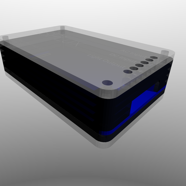
Case!
04/09/2015 at 06:50 • 0 commentsOk, I admit it, I have gotten a bit ahead of myself. I've gone ahead and made a case for the ESPLux before I have even started working on the board. I'm hoping to be able to fit the board into the Sick of Beige DP7043 case. If not, that's ok, I made it in OpenSCAD. I'll just update the code to fit the next size up.
I was looking for cases in all the usual places, and they all either look crap, are a one off, or are expensive. I was keen to have something that won't go away in the future, and the Sick of Beige standards are a great place to start off at.
![]()
The blue layer towards the bottom of the sandwich is the PCB. If you have been following along, I've been ordering different coloured boards from DirtyPCBs along the way. So far, my favourite is white, so I'll probably stick with that for the final version. I have access to a laser cutter, and so will just cut a bunch of perspex up to build up the sides. Depending on how high the caps are etc, I can increase or decrease the number of layers as required. The top will have a clear perspex lid so that you can see through to the components inside, and will have cutouts so you can get your screwdriver in to tighten/loosen the screw terminals for the inputs/outputs. I have decided on going with screw terminals rather than any particular standard at this time. I figure it leaves the most options available for whoever is using it. If you are using a standard MR16 globe, you could put those flyleads on, if not, just wire it up however you need.
I'm thinking I will probably use this for the lighting on my workbench in the garage too, which is just a 12vDC power supply with some LEDs hanging off it. I will put a screw terminal on for a DC input, that way you don't have to populate the bridge rectifier if you don't need it.
-
PSU Breakout
04/08/2015 at 13:51 • 0 commentsA few more spare hours, another project log, and another breakout board.
This, to be honest, is a complete stab in the dark for me. I have no idea what the outcome of it will be. I found the LM2596 (datasheet) and I thought it looked like it would fit the bill quite nicely. It seems to be ubiquitous enough that I am not going to get stuck with a part I cant source in the future, and deals with a much wider range of input voltages than I expected, plus it is most efficient at 12v for a 3.3v output. Hopefully this will be able to cope with a bunch of LED drivers as well. Searching for more information on it, I found a stack of breakout boards already exist for this. All good, I still need to make sure my parts work fine.
Searching around the dirtyPCBs/Dangerous Prototypes site, I stumbled across Sick of Beige. I wish I had found it before I built my first board! I have designed this board as the DP5050 standard, It had enough room for me to play around, and also fit under the dirtyPCBs 5x5 price bracket. Anyway, I will see how it turns out - if it works out, I'll try use one of the 'Golden Rectangle' sizes for the final product. I'd love to fit it into the DP7043, but will see.
Anyway, back to the board. The components used are my best guesses for the right values, based on what I can see on the datasheet and the breakout boards on fleaBay. Worst case, I can throw some bodge wires in and hack in different value components to get what I need. I will see what the output voltage looks like when I have it in my hands. I am struggling to find an SMD rectifier that is beefy enough to deal with the power that I want to play with, so ended up with this. I hope it works, if not, I should still be able to just pump 12v DC in through the DC OUT terminals to test the rest of the circuit. If you know of an option that is more suitable for me, please let me know!
Here is a rendering of it:
![]()
And once again, here is the dirtyPCBs link. Please, if you want to order one, use the link here. It gives me $1 in store credit towards my next boards. Like I said above though, there is a really good chance it doesn't work. I'll update this post when I have an answer.
On another note, I stumbled across this webpage. The writer has gone through the process of testing a bunch of different power sources for downlights, and documented their effects on retrofit LED lights. This confirms what my thoughts were on the different types. Looks like I am heading down the right track. I have a switch-mode downlight power supply here somewhere, if only I could find it ...
-
MOSFET Breakout
04/07/2015 at 14:05 • 0 commentsSo I had a few hours free tonight to be able to build up one of the breakout boards. I know I said I would be working on the power supply next, but I lied. Deal with it.
I've been looking at different transformers that are out there, and have found 3 different types. Iron core, switching and an LED driver. For now, my goal is to get an iron core transformer working. Switching transformers generally have a minimum load that needs to be available before they turn on, which will make life difficult. LED drivers are generally designed to work specifically with the light they are bundled with. I am sure that there are some other options out there that provide a straight 12v source, but I haven't gotten my hands on one yet.
In any case, the source voltage on (at least) two of the above options is approx. 12vac. Part of the power supply is going to have to be a bridge rectifier to give me a DC voltage for my circuit logic. I figure, why not make the rectifier a bit more beefy and change all of the power over to DC? This will let me work with a standard N channel MOSFET to switch and dim the light on/off.
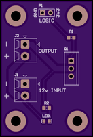
Anyway, here is my first attempt at building a circuit with a MOSFET in it. It is super simple, but once again, it is a building block not just for this project, but for any of my projects in the future that require switching. There is a simple LED onboard that allows you to see the status of the MOSFET without having a full light connected up to it. It is powered from the 12V rail.
The components required are:
R1: 100R 0603 Resistor
R2: 1K 0603 Resistor
LED1: 0603 Green LED
Q1: FQP30N06L N Channel MOSFET
J1, J2: http://www.digikey.com.au/product-detail/en/1776113-2/A97976-ND/1826839
P1: Standard 2.54mm header
![]()
![]()
Here is a link to the board on dirtyPCBs if you would like to order it. I greatly appreciate it if you buy them using the link here, it gives me $1 towards future prototype boards. In any case, the board hasn't been tested yet. When they arrive, I will post an update with my results.
Next up is the power supply. I need to get all of the parts as breadboard-able components so that I can have a play around with them before I send off a board for manufacture.
-
ESP Breakout Arrived
04/07/2015 at 04:48 • 0 commentsSorry for the lack of updates. I had planned on making more breakouts, but I haven't had an opportunity.
In the meantime, my ESP breakout boards turned up from dirtyPCBs! I think they turned out pretty neat. In hindsight though, I probably should have put a status LED on them showing if power is on or not (I'm used to my ESP-01's that have an LED on them showing power) and should have put a cutout so that the signal wasn't interrupted by the ground plane on the board. I'm assuming the signal from underneath the board wouldn't be so crash hot. Doesn't matter though, its a test board. Overall, I am pretty happy with how it turned out. The measurements I found on the net were correct. I have checked that FTDI works fine, the FTDI Power jumper works fine, and the jumper block seems to be functioning fine. Also, injecting power from an external source is working fine too. If you would like to order one of the boards, just click here. If you want to see some more images of it, here is my imgur album. Next up, I plan on playing around with the power supply for it.
![]()
-
ESP8266 Breakout
03/15/2015 at 04:39 • 0 commentsI've made the ESP8266 breakout block I mentioned in my previous post. Here's hoping that it works OK.
Here is a link to it on dirtypcbs: http://dirtypcbs.com/view.php?share=5472&accesskey=baa26ead4281fe835c0db18bac90b08a
Feel free to order one if you'd like, but no promises that it works properly just yet. I will post an update when I have ordered/received it and soldered everything together. Hopefully all is ok. [Edit: It all works fine!] There are a few things I decided to put on the board:
- On the bottom right there is a jumper block for setting CH_PD, GPIO0, GPIO2 and GPIO15 to either high or low.
- There is a standard FTDI breakout pinout on top of the board. I have a sparkfun FTDI basic breakout (https://www.sparkfun.com/products/9716) that I have been using for programming my ESP8266 ESP-1's. I figured having the proper header on there would be a useful thing.
- The FTDI Power jumper is to allow you to power the board from the breakout if that is what you really want to do. From what I've been reading, doing that is a really bad idea, but hey. If you want to try it, be my guest
- There is a dedicated 3v3/ground header, where you can plug your power supply into. For testing I will just be using my ebay special manson power supply.
- I have all the traces on the top of the board. I've not done this before, but in theory I guess you could etch this board at home yourself? The only thing would be isolating the traces below the ESP to make sure they don't short out the bottom of the board if that is a thing.
I'll upload the gerber files to github soon.
-
Building Blocks
03/13/2015 at 09:24 • 0 commentsHi all,
I've been thinking of building this project for a while now, but haven't really had the opportunity to start it until recently. After moving into a house, and looking up at the downlights, I looked into different options of controlling them. Philips Hue was the first to pop up. They are amazing lights, but they don't really fit the bill for me. They don't have an MR16 bulb here in Australia, the multiple colours thing is a bit overkill for what I want, they aren't outdoor rated, and they cost an insane amount of money. A few other options popped up as well, but most of them were either very expensive, or simply didn't have the 12v MR16 bulbs that I wanted.
After seeing a significant number of ESP8266 posts pop up on Hackaday, I thought I should get some to play around with. I figured this would be a good starting block for me to work from.
Having very little background in electronics, I am a bit cautious of designing up a first revision of the schematic (even if it is quite simple) and sending it off for fab without building up test boards first. I am assuming that this is fairly commonplace in the industry, however, when I thought of the idea I felt as though it was a bit of a breakthrough for me. Splitting the project up into smallish chunks will hopefully allow me to test each of the individual parts without confusing the daylights out of me. Additionally, for future projects I'll be able to refer back to these and have something that I know has worked for me previously. I can see three different blocks that I should build up so far.
- An ESP8266 breakout
- A switchmode power supply to convert the 12vac from the transformer into something I can use
- The switching circuit for controlling the downlight itself
Time to get cracking!
ESPLux - Smarts for your downlights
A circuit you can place inline with your existing low voltage lights to allow for wireless control