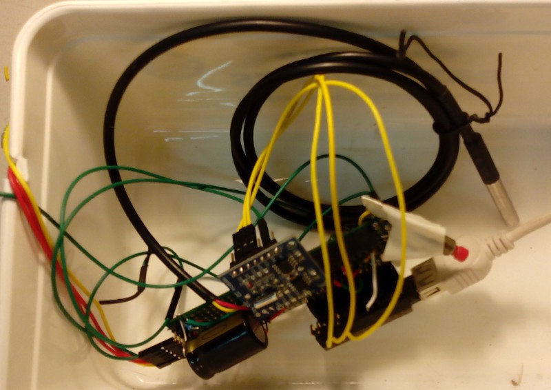
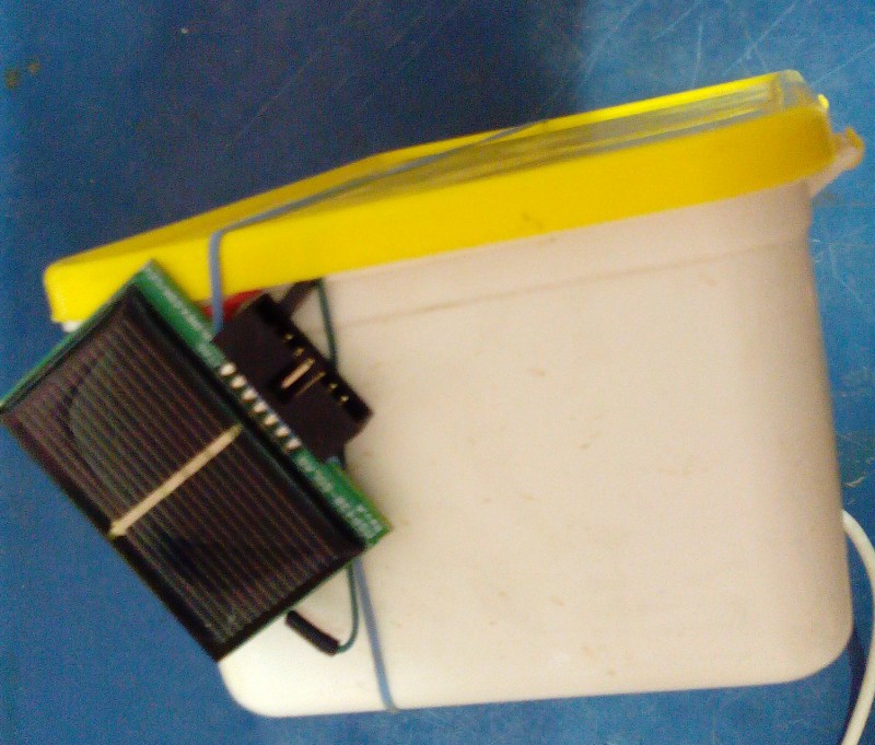
So I managed to build a data logger over the weekend from an Arduino Leostick, a TinyRTC, DS18B20 and MSP430-SOLAR. In the end I didn't need the opamp, after verifying that the solar voltage definitely capped out at about 2.5V. So it monitors four voltages: Solar Panel, SuperCap, input to the stepup regulator (and thus the capacitor current) and the regulated 3v3. Also logs temperature and time.
As part of this exercise it struck me that I probably had to high a current limit resistor on the supercap as on examination the MSP430 features two diodes that drop up to 0.8V, presumably for limiting charge voltage to a NiMH or NICAD.
At also occurred to me that many small solar charge systems are simple but inefficient. Due to the diode there would be energy at low light that gets "lost", and further energy is lost through current limiting resistor on discharge. Ideally there would me some kind of MPPT between the panel and the supercap and the step up regulator (or perhaps all built into one)... so possibly some work to do here in a couple of months after the first system prototype is going.
Anyway, pictures of my dodgy work :-) Its been a while (read: a few years, apart from the radio miniconf at LCA2015) since I had the soldering iron warm for this long. I probably should have stuck to breadboard I would have been done a few hours earlier. But it tuns out its like riding a bike...


(Photos (c) @pastcompute CC-BY-NC)
 pastcompute
Discussions
Become a Hackaday.io Member
Create an account to leave a comment. Already have an account? Log In.