Pictures from construction of the Muffsy Phono Preamp.
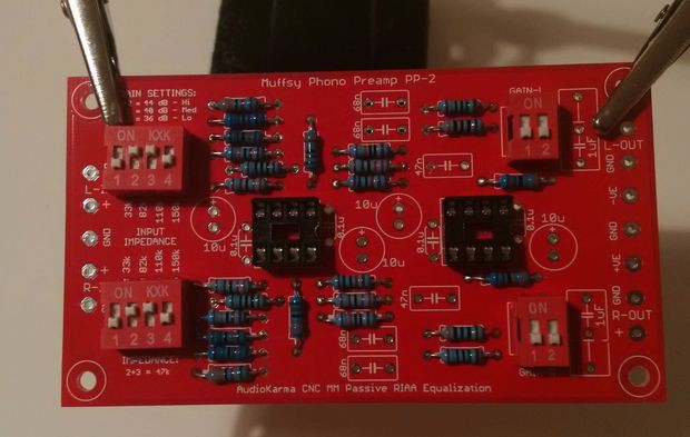
First to go in are all the resistors, as the are closest to the board. Always start with the components closest to the board. When some of the larger components are soldered in place, it will be difficult to fit the smaller ones.

Next in line are the switches and the sockets that will hold the opamps. All of these components must be oriented correctly.
That done, it's time for the smaller capacitors. Start with the ceramic disc capacitors close to the sockets, continue with the 47nF and 68nF polyester film capacitors in the RIAA filter and end with the two 1uF output capacitors.
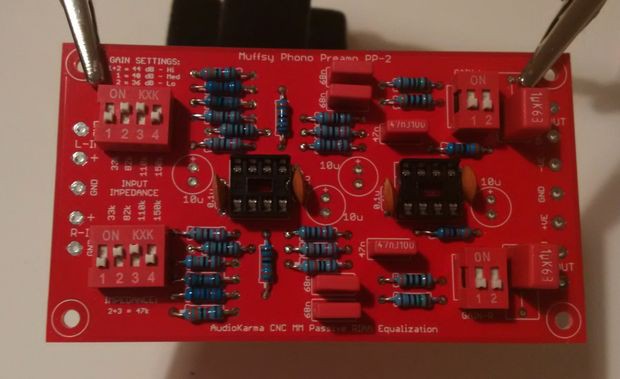
Finally solder the 10uF electrolytic capacitors in place, mind the orientation.
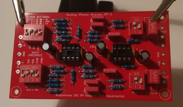
That's it, the preamp PCB is fully assembled.
Discussions
Become a Hackaday.io Member
Create an account to leave a comment. Already have an account? Log In.