facelessloser
Video
Quick demo video of the hardware in action
Update video
The beginning
Another year another hackaday prize, (I hope this is going to be an annual affair). After entering last years contest with a project I just happen to be working on at the time I thought I would put a little bit more effort into this years entrance.
I drew imperative from This post on hackaday where they used a vibration sensor made for robots that uses a piezo speaker/sensor to read vibrations. They repurposed it to read your pulse on your finger. After seeing this I thought I could use it as a medical based sensor/monitoring kit. I racked my brain looking at all the different arduino sensor so see what else I could add to this. The only sensor that made sense to team up with the now heart rate sensor is a temperature sensor
Testing the piezo theory
Now that I had decided on what my project was going to be I could start fleshing the hardware . I started with the piezo vibration sensor to see if I could get it working for myself.

I copied the code from This blog post to as a starting point, To my disappointment it wouldn't pick up my pulse with the piezo strapped to my finger. This was a real blow to my project because if I couldn't get this to work I would have to go back to the drawing board as they say. Not to be too discouraged I tried the piezo sensor on my wrist because this is where you normally take your pulse, IT WORKED I couldn't believe it. I did have to lower the threshold to make it easier to pick up my pulse.
Trials and tribulations with temp sensors
The thing I was looking for in a temp sensor was something that was enclosed and water proof so when I seen the DS18B20 I looked just what I wanted.

One trying the example sketch and library everything looked good until I added the code for the piezo sensor, that's when I found out that the library was too slow so It wouldn't let me read the piezo sensor fast enough.
Back to the drawing board to try and find a replacement sensor. My attention turned to the LM35 as it being a similar size to the DS18B20 without its metal enclosure.

My idea was to remove the DS18B20 from its enclosure and put the LM35 in its place. One good things about the DS18B20 is that they use plenty of sealant to ensure its waterproff but that means its impossible to remove. The only way i found to remove it was to drill out of its enclosure, only then I realised that the LM35 was a 1mm too big so I sanded it down a touch but this destroyed the ability of the LM35 to read temperatures. In the end I just settled with using a bit of heat shrink tubing about the base of the LM35.

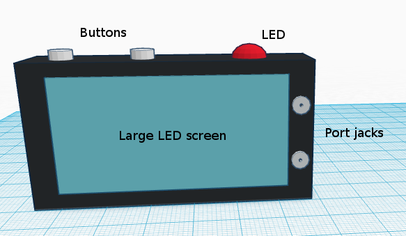
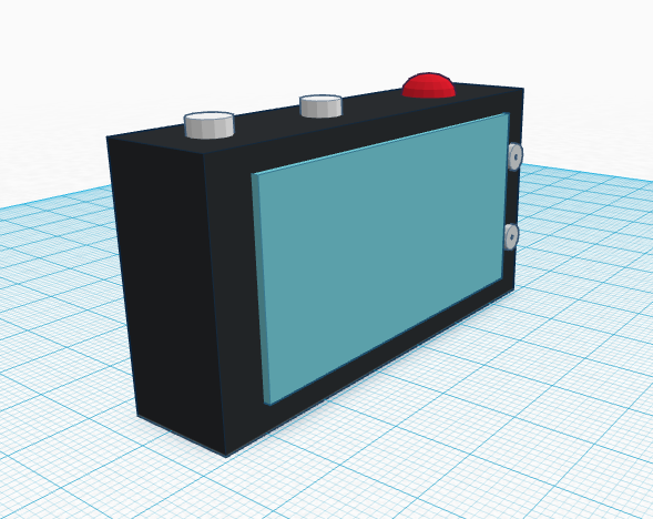
Picking the enclosure
Like with all my previous projects I like to try out different things. Because this project didn't have to be small or portable, It let me be less picky about the enclosure. I wanted it to have a test equipment vibe and had been eyeing up these which would be big but not too big

Also what I liked was that it all came apart, The front and back panel would come off and also the top and bottom. This made it much easier to work on the panels and if I messed it up would be easily replaced too.
The power solution
When most people think about powering a project they initially think of a lipo battery teamed with a cheap lithium battery charger which is a good solution. I like to use 18650 lithium battery which are significantly cheaper for high-capacity but a bit bulky, Also you can rip the guts out of a 18650 phone chargers because the PCB can be used for charging the battery and powering your project all on one board.

I went with two 4200mAh battery to give the project a good battery life because it will be used off the grid with charging few and far between.
As the project might be run off a solar cell or plugged into the mains for long perides of time I wanted a way to power it but not charge the battery all the time. I added a swtich so you could just power #T_H_S or power and charge the battery, That way you wouldn't have to worry about over charging the battery

This is the layout for the power/FTDI side of #T_H_S. I added a few diodes so the battery's wouldn't charge its self by power coming out of the FTDI board.
I ordered a 5v 500mAh 2.5 watts solar cell to power #T_H_S. Being in the UK I wasnt sure if we would get enought sun to get any decent voltage out of the panel.

I could get almost 6v out of the cell in strong sunlight but now I needed a way to boost and regulate it. I bought a DC -DC boost converter to give the solar cell enough juice to power #T_H_S plus it had a female usb port.

I mounted the solar cell on a piece of PVC meant for a window ledge so it was L shaped, This give it a slight angle so it would catch the sun a little better

You can't really see in the picture but the solar cell is powering it and could also charge the 18650 battery's too. Not sure how long it would take to charge the battery's but I'm guessing awhile.
I wanted to have as many way to charge/power #T_H_S so I bought a hand crank phone charger.

It has a full size female usb port so I can power #T_H_S. It doesnt take much cranking to get enought current to power #T_H_S but I think it would take some time to charge the battery's up. Now with the solar cell and the hand crank it can quite easily be powered off the grid.
PCB design
Like every phototype I always start out on a arduino uno and a bread board. Once you get the hardware nailed down I can move to a digital version of the bread board desigh for this I use Fritzing, it also makes it easier to lay out and cross frefurance the final board.

I use Kicad to do my PCB layouts because its free, open source and cross platform what more could you ask for. If you want to get started on Kicad I would suggest you check out Contextual Electronics youtube channel. Ive made quite a few boards now for the last few projects, Its deferenly a skill you should consider learning.
I had a few slip ups with the design of my board. Firstly I made the thought holes for the FTDI headers too small and the same for the speaker holes. I only realised the holes were too small after I received the board but lucky the holes were just big enough to solder some thin wires from them.

Always double check your dimentinos of your PCB and hole sizes before getting your board spun. I mostly get my boards made at OSHpark because there cheap and fairly quick delivery even to the UK.
A few bells and whistles
After I got the main code nailed down and doing the basics I started to add a few extras. Firstly I wanted it to make a sound like a beep every time it detected a heart beat just like the hospital ones do and while I was at it I thought it might as well blink an LED.
I wanted it to dispaly the battery levels so I knew if it needed charging or that it was being charged too.

To achieve this I wired straight from the battery (not from the 18650 battery charger PCB) to an analog pin and used this code from This website for the basic reading. Check out my battery precent code
#include <LiquidCrystal_I4C.h>
#include <Wire.h>
LiquidCrystal_I2C lcd(0x27,16,2); // set the LCD address to 0x27 for a 16 chars and 2 line display

int fullBattery = 880; // Battery max value
int emptyBattery = 300; // Battery min value
int batteryPercent; // Batttery percent

unsigned long waitUntilBattery = 10;
long previousMillisBattery = 0;

uint8_t battery[8] = {0xe, 0x11, 0x11, 0x11, 0x1f, 0x1f, 0x1f, 0x1f}; // Custom char battery
uint8_t charging[8] = {0x4, 0x4, 0xe, 0x1f, 0x11, 0x11, 0x1f, 0xa}; // Custom char battery charging

void setup() {
 lcd.init(); // Start up the lcd
 lcd.backlight(); // Turn on the lcd backlight
 lcd.createChar(3, battery); // Custom Char battery
 lcd.createChar(5, charging); // Custom char charging
 Serial.begin(9600); // Start serial
 }

void loop() {
 unsigned long currentMillisBattery = millis();
 if (currentMillisBattery - previousMillisBattery> waitUntilBattery) {
 previousMillisBattery = currentMillisBattery;

 int batteryRead = analogRead(A2); // Reads battery pin
 batteryPercent = map(batteryRead, emptyBattery, fullBattery,0 ,100); // Maps the battery percent from high and lows

 if (batteryRead <= 400 ) {
 //Serial.println("Charging");
 lcd.setCursor(10,1); // Set cursor
 lcd.print((char)5); // Print custom battery icon to LCD
 lcd.print("Power"); // Print to the LCD
 }

 else {

 if (batteryPercent >= 100) {
 lcd.setCursor(11,1); // Set cursor
 }
 else {
 lcd.setCursor(12,1); // Set cursor
 }
 lcd.print((char)3); // Print custom battery icon to LCD
 lcd.print(batteryPercent); // Print to the LCD
 lcd.print("%"); // Print to the LCD
 }
 }
 }
Code and design files
As with all my projects I put all my files and code up on my github page. There are quite a few projects up on there now so have a look around and have a look on my blog too
Library licences
Liquid cystal i2c library - Under creative commons license 3.0
rtttl library - Can't find a license for
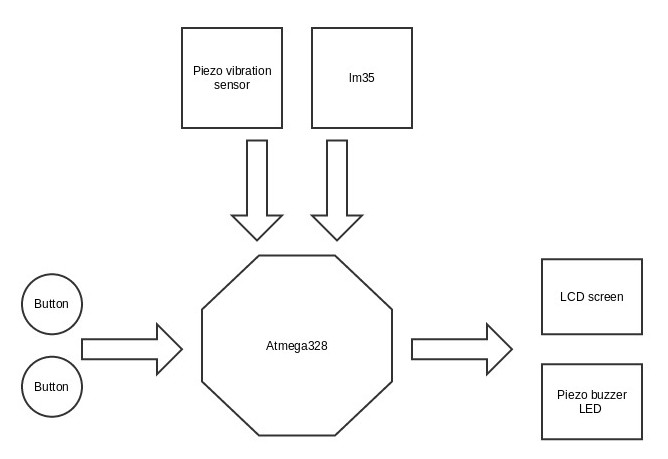
System design diagram
productized