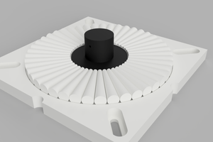
The first step was the make sure the bins would both physically fit in the cupboard – and they did. By placing them sideways (Which actually made a lot of sense in this case) they fit with just enough space around them. This also allowed us to test a MVP – would having the bins in the cupboard work for us? After a week, we didn’t hate it, so on to the next step.
Time to jump in to Fusion 360, and have a bit of a play around with a few ideas and some dimensions.
My first thought was to have attach some drawer runners to two rectangles of wood that ran around the inside of the cupboard, but this seemed overkill, and the dimensions were a little too tight to make it really work. Next, I wondered about 3D printing some brackets that would hold the drawer runners. I jumped on to the Bunnings web site to find some drawer runners, and I found some likely candidates for just $11. The problem was (as always) no accurate design drawings or dimensions.
But for $11 (and Bunnings’ generous returns policy), I was willing to take a punt.
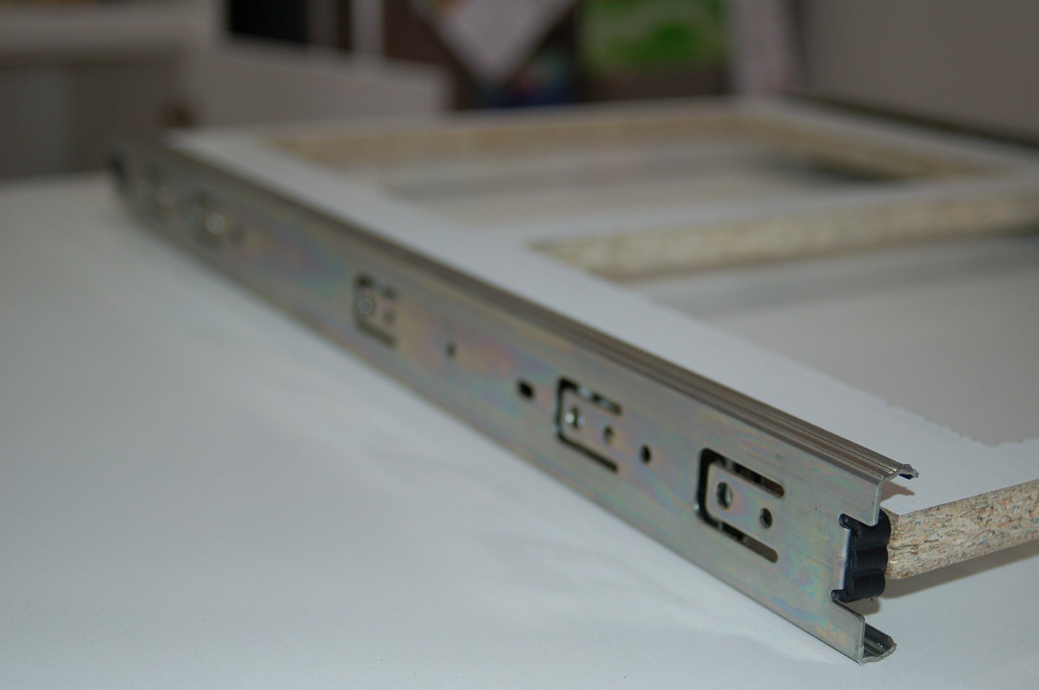
The next problem was how to attach the brackets to the walls of the cupboard. 3D printed plastic nubs probably wasn’t going to cut it – I could see them snapping off in the holes. Next, I thought about embedding some 5mm metal rod, or perhaps removing the plastic off the existing shelf supports. I then did a quick search on the Bunnings website and found these all metal shelf supports with metal lugs that would work perfectly (for a grand total off $2.67!). Off to Bunnings!
One sausage sizzle later, I had the bits I needed.
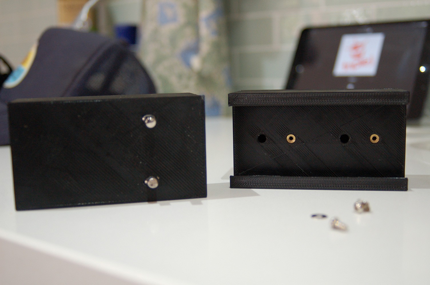
Now I had the dimensions of the drawer runners and the supports, I whipped up a quick design, and 2 hours later I had printed the first bracket to test for fit. Initially, I was going to rely on brass inserts and screws to secure the runners, but I added a small curve to add a some additional support. This worked out better than expected – the curves would happily hold the runners without the screws (although I still added two screws on the back off the runners to keep them in place when pulling out the bins). When it came to attaching the metal inserts, I thought of using heat like I did with the brass inserts, but it turned out a hammer and friction was enough to hold them in – and the platform that the bins would live in would actually push the runners out, holding the whole thing together.
So over the next 6 hours, I printed the remainder of the brackets.
Once the were done and installed, I could get final measurements for the shelf. This was where designing it in CAD helped – according to my calculations, it would need to be 420mm, and I was dead on. Initially, I was going to buy some melamine coated MDF, but then I decide to cut the existing shelf (which just so happened to be melamine coated MDF) to size.
Cutting the 500x550mm panel to 420x550mm was easy work, but the internal holes for the bins were a little more challenging as I couldn’t find my jigsaw. I used a multisaw, which in theory should be the same, but was ended up being slower and more difficult to use. As a result, the holes looked like it was cutout by a drunk monkey. Nothing a bit of rasping couldn’t fix. Besides – the bins will cover a multitude of sins. All in all, the result was good enough.
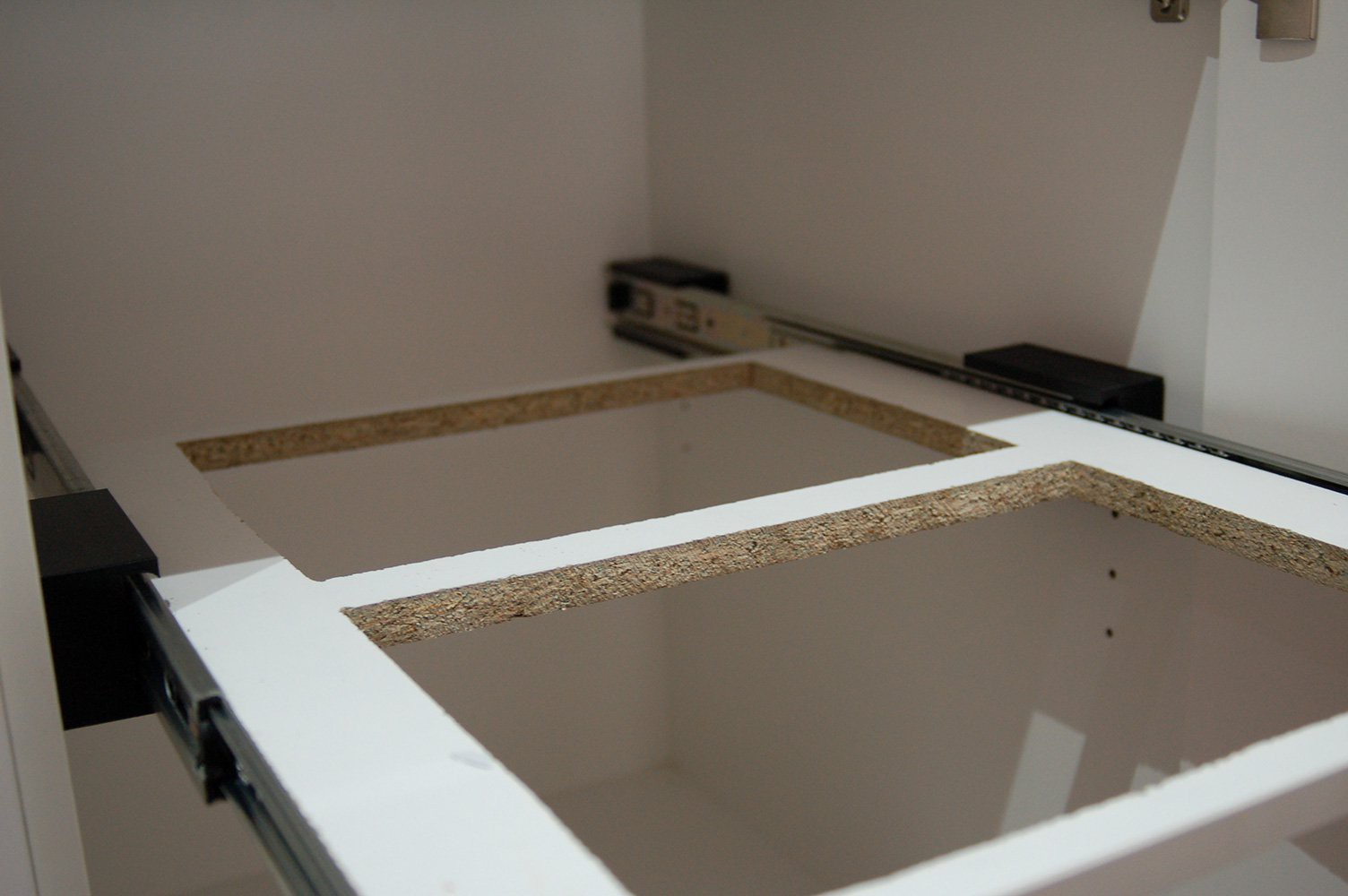
It was at this point, I made a minor mistake in drilling the holes for the runners – they are offset from centre, and I drilled one side on the wrong side, but that was easy enough to fix, just by drilling them on the other side of the centre line.
Putting it together was slightly more challenging, as I needed to screw in the support screws whilst in-situ, and had to do a bit of a contortion act to get them in. But once it was in, it all worked really well. The shelf could have possibly done with 1mm extra cutout, so the run was a little smoother, but it’s totally fine as is.
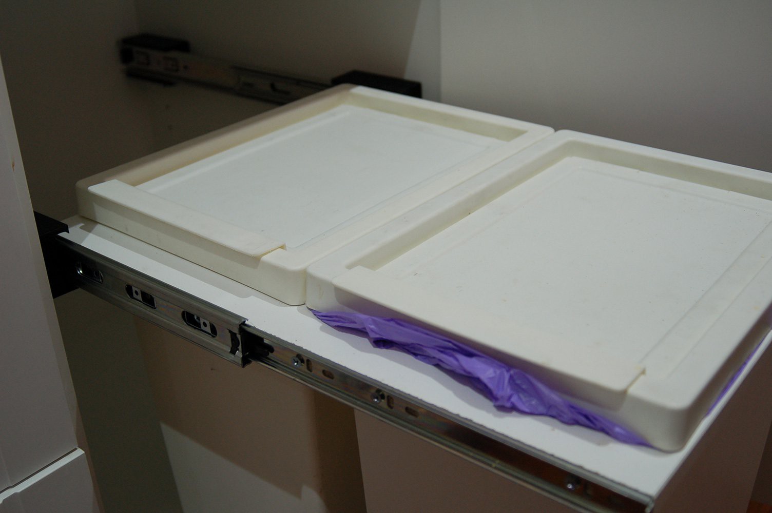
The other thing I would change it to make the non-door side thinner, so the there wasn’t such a massive gap between the cupboard wall...
Read more » Myles Eftos
 Boris van Galvin
 Øystein
 joseph