 kender.arg
I've got four EastRising LCD modules from www.buydisplay.com.
I've got a Teensy 3.0 from Paul Stoffregen
I've got a workspace stocked with all kinds of tools and components.
The LCD modules comes with a FPC cable so I ordered some
I then breadboarded up what I think is a fairly accurate representation of the ERC160160-2 Series Interfacing Example Drawing
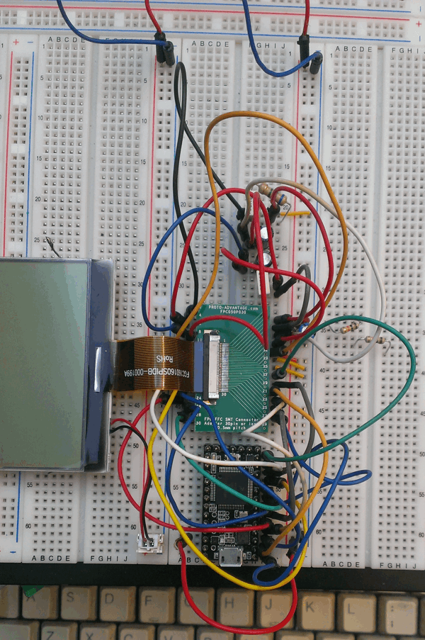
And a diptrace schematic of same.
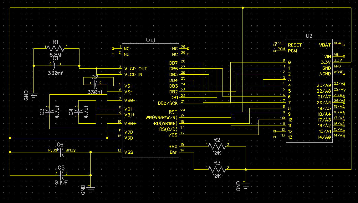
I've used the Teensy 3.0 rather than an 8080 MPU as used in the example.
I'm also using the Teensy 3.3v output to power the display at the moment. I'm not yet sure about how I want to power the entire project later on. Battery? 5V wall-wart adapter with LM1117 conversion to 3.3v? Usb cable to Teensy?
The single display (including backlight) already consumes 92mA so that could become a problem later.
The display modules use the UC1698 driver chip, but unfortunately not all of its capabilities are available. Most unfortunate of which is that the SPI mode of the UC1698 is not available :(
The pins (db13 & db15) needed to configure the driver for serial mode are not available on the cable. So the only choices left are the 8-bit 8080 or 6800 parallel modes. Which requires lots of pins (12) to address the display. The plan is to connect all the pins of all three displays together, except for the CS pins.
Fortunately the Teensy 3,0 has plenty of pins available.
I've also taken the ERC160160-2 Series Demo Code and ported the important bits:
/*
Quick & dirty port of main bits of demo code.
*/

const int D0 = 0;
const int D1 = 1;
const int D2 = 2;
const int D3 = 3;
const int D4 = 4;
const int D5 = 5;
const int D6 = 6;
const int D7 = 7;

const int WR1 = 8;
const int WR0 = 9;
const int CS0 = 10;
const int CD = 11;

void setup()
{
  Serial.begin(9600);
  delay(1000);
  Serial.println("Setup");

  pinMode(D0, OUTPUT);
  pinMode(D1, OUTPUT);
  pinMode(D2, OUTPUT);
  pinMode(D3, OUTPUT);
  pinMode(D4, OUTPUT);
  pinMode(D5, OUTPUT);
  pinMode(D6, OUTPUT);
  pinMode(D7, OUTPUT);

  pinMode(WR1, OUTPUT);
  pinMode(WR0, OUTPUT);
  pinMode(CS0, OUTPUT);
  pinMode(CD, OUTPUT);

  init();
}

void output(uint cl)
{
  digitalWriteFast(WR1, HIGH);
  digitalWriteFast(WR0, LOW);
  ((cl & 0x01)) ? digitalWriteFast(D0, HIGH) : digitalWriteFast(D0, LOW);
  ((cl & 0x02)) ? digitalWriteFast(D1, HIGH) : digitalWriteFast(D1, LOW);
  ((cl & 0x04)) ? digitalWriteFast(D2, HIGH) : digitalWriteFast(D2, LOW);
  ((cl & 0x08)) ? digitalWriteFast(D3, HIGH) : digitalWriteFast(D3, LOW);
  ((cl & 0x10)) ? digitalWriteFast(D4, HIGH) : digitalWriteFast(D4, LOW);
  ((cl & 0x20)) ? digitalWriteFast(D5, HIGH) : digitalWriteFast(D5, LOW);
  ((cl & 0x40)) ? digitalWriteFast(D6, HIGH) : digitalWriteFast(D6, LOW);
  ((cl & 0x80)) ? digitalWriteFast(D7, HIGH) : digitalWriteFast(D7, LOW);
  digitalWriteFast(WR0, HIGH);
}

void write_com(uint para)
{
  Serial.print("Command: ");
  Serial.println(para, HEX);
  digitalWriteFast(CS0, LOW);
  digitalWriteFast(CD, LOW);
  output(para);
  digitalWriteFast(CS0, HIGH);
}

void write_data(uint para)
{
  digitalWriteFast(CS0, LOW);
  digitalWriteFast(CD, HIGH);
  output(para);
  digitalWriteFast(CS0, HIGH);
}

void init()
{
  delay(200);
  write_com(0xe2); // set system reset
  delay(100);  //delayms 200ms

  /*power control*/
  write_com(0xe9);			//Bias Ratio:1/10 bias
  write_com(0x2b);			//power control set as internal power
  write_com(0x24);			//set temperate compensation as 0%
  write_com(0x81);			//electronic potentionmeter
  write_com(0xbf);

  /*display control*/
  write_com(0xa4);			//all pixel off
  write_com(0xa6);			//inverse display off

  /*lcd control*/
  write_com(0xc4);			//Set LCD Maping Control (MY=1, MX=0)
  write_com(0xa1);			//line rate 15.2klps
  write_com(0xd1);			//rgb-rgb
  write_com(0xd5);			//4k color mode
  write_com(0x84);			//12:partial display control disable

  /*n-line inversion*/
  write_com(0xc8);
  write_com(0x10);			//enable NIV

  /*com scan fuction*/
  write_com(0xda);			//enable FRC,PWM,LRM sequence

  /*window*/
  write_com(0xf4);			//wpc0:column
  write_com(0x25);			//start from 112
  write_com(0xf6);			//wpc1
  write_com(0x5A);			//end:272

  write_com(0xf5);			//wpp0:row
  write_com(0x00);			//start from 0
  write_com(0xf7);			//wpp1
  write_com(0x9F);			//end 160

  write_com(0xf8);			//inside mode

  write_com(0x89);			//RAM control

  /*scroll line*/
  write_com(0x40);			//low bit of scroll line
  write_com(0x50);			//high bit of scroll line

  write_com(0x90);			//14:FLT,FLB set
  write_com(0x00);

  /*partial display*/
  write_com(0x84);			//12,set partial display control:off
  write_com(0xf1);			//com end
  write_com(0x9f);			//160
  write_com(0xf2);			//display start
  write_com(0);				//0
  write_com(0xf3);			//display end
  write_com(159);			//160

  display_address();
  display_white();

  write_com(0xad);			//display on,select on/off mode.Green Enhance mode disable
}

void display_address()
{
  write_com(0x60);			//row address LSB
  write_com(0x70);			//row address MSB
  write_com(0x12);			//column address MSB
  write_com(0x05);			//column address LSB
}

void display_black()
{
  uint i,j;
  for(i=0;i<160;i++)
  {
    for(j=0;j<81;j++)
    {
      write_data(0xff);
    }
  }
}

void display_white()
{
  uint i,j;
  for(i=0;i<160;i++)
  {
    for(j=0;j<81;j++)
    {
      write_data(0x00);
    }
  }
}

void loop()
{
  display_address();
  display_black();
  delay(1000);
  display_address();
  display_white();
  delay(1000);
}
What I haven't got is any kind of reaction on the display.
I suspect there's something wrong with the power-side of the display module. And this is where I really run in to my inexperience. I'm by trade a software guy. Easy, everything is 1 or 0. This analog stuff is throwing me for a loop with all the capacitors, resistors, different voltages, current flows etc.
I'll get into debugging in another post next weekend hopefully.
Discussions
Become a Hackaday.io Member
Create an account to leave a comment. Already have an account? Log In.