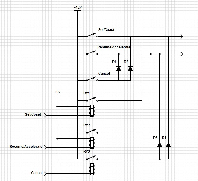
The existing cruise switch is wired as shown in the top half of the schematic below. Diodes are used along with the switches to send 3 inputs over two wires. I plan to replicate that setup using relays that will be controlled by my project. This is shown in the lower half the schematic. I can't think of a use for the cancel control for my project, although I may include the connections since it will be easier to do now than to add later.
Discussions
Become a Hackaday.io Member
Create an account to leave a comment. Already have an account? Log In.