-
Hello World!
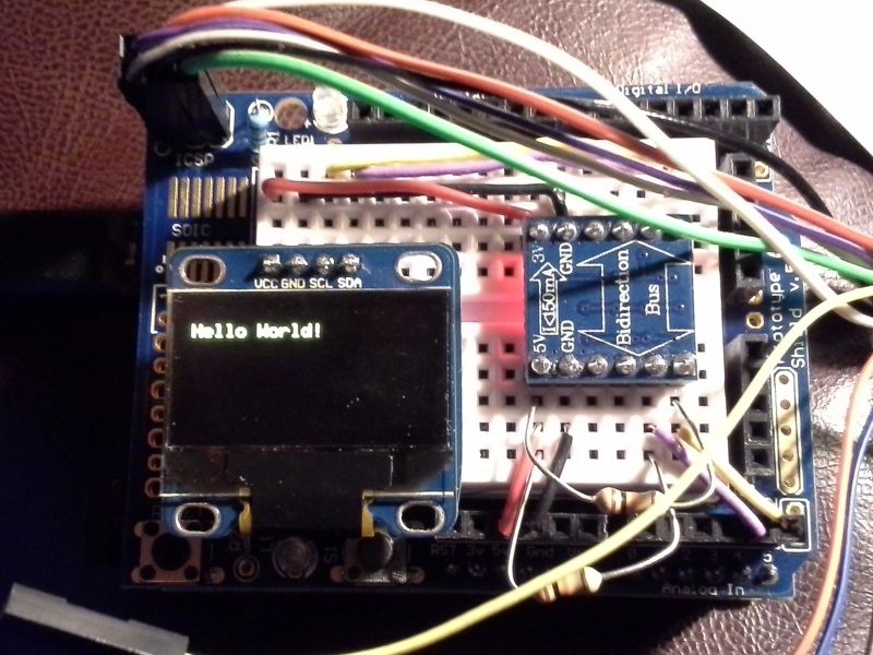
05/08/2015 at 16:47 • 0 commentsIn the previous log I mentioned that I had gotten the test Hello World file from the u8glib library to compile in Atmel Studio, but I had to include all the various library files in the project. I revisited that, looking at how I could use the u8glib as an actual library.
The u8glib wiki has a page about using with the AVR. Under the Install section, it links to the instructions for the m2tklib. I followed those instructions for building a static library, but stopped at the Create Example Project part. I'd like to reuse this library for multiple projects and don't want to have to rebuild it each time I have a different Atmel Studio solution (although you do have to define F_CPU, so you'd need to rebuild it if you were using it on a board that ran at a different frequency). I built the project as it was, and then went back to the solution I used originally (where I added all the library files I needed individually to the project). Deleting all of the library files from that (just keeping the hello_world.c file), I added the libu8glib.a as a library (this was just a guess). I tried building it, and it completed. No warningd, no errors. Which made me suspicious. :)
I didn't have time over that lunch break to program it, so it had to wait until last night. I programmed the board (after soldering an ISP header to the breadboard shield), and it worked!
![]()
So I think I've pretty much used up all the good luck on the project right there. I suspect from now on small advances will require tons of work. A few guesses on how to do things and it all works out just like it should? I'd like to take credit for getting it all to work, but I think it was just luck. But I'll take the luck.
Now I need to think through what my next step is. I'll probably make the changes that display the '65' like I had previously working with the Arduino environment, but that should be quick. Next I'll probably work on connecting the GPS to the AVR and parsing the data that it gives me. With my display working I'll have a nice way to see that it's working properly.
Before doing that, though, I'm going to read through the u8glib page a bit more. I think the Google Code layout makes it look less documented than it is. Finding the great steps to make a library hints that it's probably documented well. I'm not sure if I'll use the associated m2tklib in my project, but I'll have to look it over so I know what's available. Some neat stuff there, I think.
-
Progress with Atmel Studio
05/01/2015 at 19:28 • 0 commentsI've done a little bit of work since my last project log. I got distracted by another project, but that has mostly ended so I think I'm back to this one. :)
I did finally manage to get the u8glib sample program to build in Atmel Studio. This was mostly through including the various source files from the library into my project until it would build without errors. I looked briefly at the library section of the project, but it seemed like I needed a compiled library of some sort for this? Having finished, though, I think I need to look again at adding a library. That would save a bunch of work tracking down functions and would make it much more portable to new projects.
As I said, though, I did get it to build. And then I decided I should probably not start programming the VISduino board from Atmel Studio with complex software but should try something simple. So I followed this example to make sure the tools and methods worked. After compiling and then programming (via ISP) the program to make sure it worked, I attempted to connect via debugWire. Atmel studio first said it needed to set the DWEN bit to enable debugWire. I had previously read a note from Atmel warning that if the SPIEN bit was disabled and the DWEN bit was then disabled you couldn't program the board without using high voltage programming. Since the AVR on this board is SMT, I didn't want to mess it up. So I was nervous about this step.
But I said yes, and then it popped up an error saying it couldn't connect via debugWire. "Great" I thought. "I just messed up my board."
I stared at it for awhile, and then I remembered my last project log. The part about removing the capacitor on the rest line. Which I of course had forgotten to do. After doing that I was able to connect and step through the code.
Next step is to program the board with the display test code and see how that works.
-
Plan of attack
04/13/2015 at 19:10 • 0 commentsNot much to show for today's work, but sometimes coming up with how to do something is harder than actually doing it. Or so I tell myself. :)
I've decided I want to forego using the Arduino IDE. The ease of use is great, but I really miss having a debugger to use. Not that I've had anything I've needed to debug yet, but I'm sure I will soon. I'll continue to use an Arduino board, but I'll use Atmel Studio along with and Atmel JTAGICE mkII for programming and debugging.
So, towards that goal, I need to modify an Arduino. I ordered a few VISduino boards off of eBay from China. These are very inexpensive (~$5) boards that are similar to an Arduino UNO. I'll need to both program over the Arduino bootloader and unsolder a capacitor to use these with the JTAGEICE, so I wanted to leave my 'real' Arduino board intact. The VISduino boards arrived a few days ago. On one the crystal for the CH340G USB to serial chip had come loose (bad solder joint?), but I was able to resolder that easily. Both were programmed initially with the Blink program, and I was able to confirm that I could program my own code.
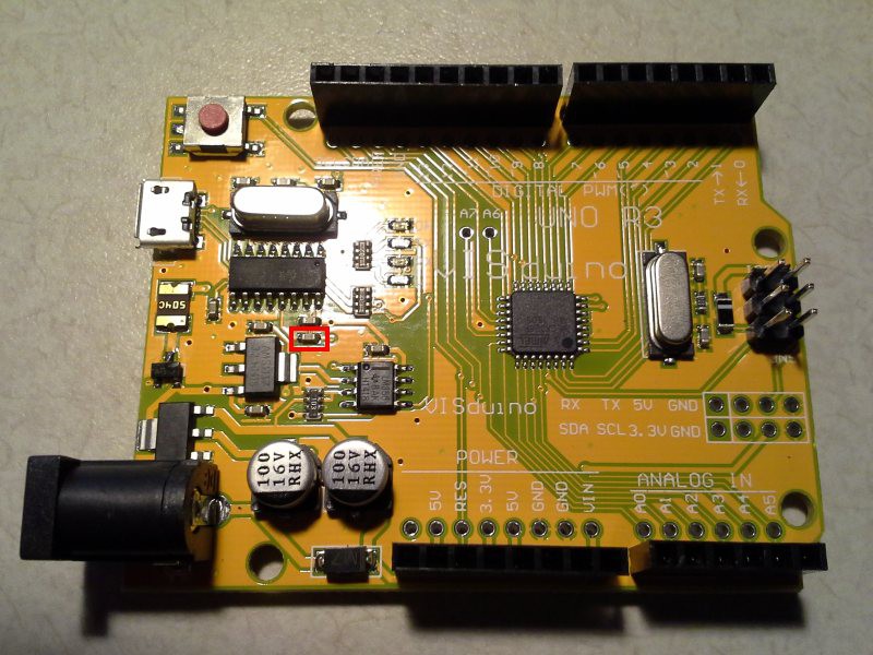
These are the instructions I'm going to generally follow for using the JTAGICE. The first step is to unsolder the capacitor that is attached between the DTR pin of the USB to serial convertor and the reset line. Looking at the board along with a pinout of the ATmega328 as well as the CH340G pinout, it looks like the capacitor 'squared' in red below is the capacitor to remove. I didn't get to that today, but perhaps tomorrow.
![]()
I did upload the example code mentioned in the last log using the u8glib library to this board to make sure it works with my setup before I start modifying it. It looked pretty much like the photo from last time, but with a yellow board underneath instead of a blue one. The breadboard shield sure makes it easy to swap things around.
-
Graphics Library Tests
04/10/2015 at 18:38 • 0 commentsLast night and today over lunch I worked on displaying some minimal text with the Adafruit library and also with the u8glib. The u8glib was already setup to use the address of my display, so the issue I had last time was just that my SCL and SDA lines weren't connected properly. The example Hello World program worked fine.
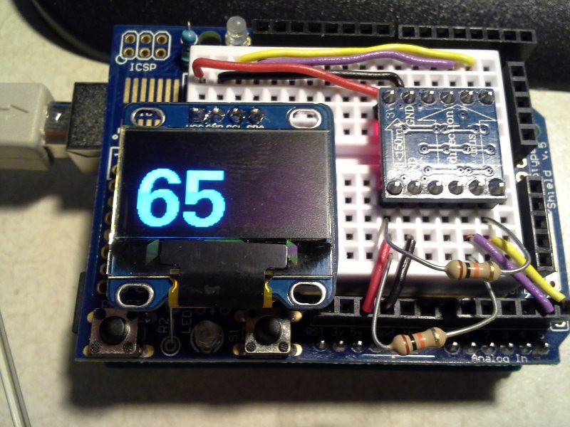
I modified it to display a large 65 as shown in my initial mockup image. The u8glib uses fixed size fonts. The 49 pixel Free Universal font was just a little too big, causing the top parts of the numbers to be in the yellow part of the display when the numbers were as far down as I could put them (which makes sense, since the yellow part of the display is 16 pixels and the blue is 48). Using the 42 pixel Free Universal font, I got this:![]()
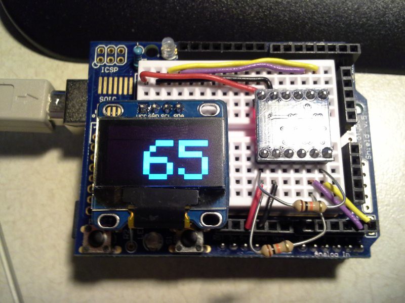
Using the Adafruit library and stripping down the example program to just display "65", I got this:
![]()
The Adafruit library obviously uses a scaled font.
I like the display from the u8glib much better, but that's to be expected from a fixed size font (well, on devices with these specs). I'll have to see how many font sizes I want to use (maybe I can get by with just the large number font (which just contains numbers, and so it is reasonable in size) and a smaller font for the status text.
Regarding code sizes:
u8glib - ROM: 6810 bytes RAM: 236 bytes
Adafruit - ROM: 10540 bytes RAM: 1526 bytes
The frame buffer for this display is: 128*64/8 bytes = 1024 bytes. So it seems clear that the u8glib buffer is not statically allocated, and the Adafruit one is. It could be that the u8glib buffer is allocated only when it needs it, or perhaps it grabs it and holds onto it. Since I don't need to keep the frame buffer around after it's been sent to the display I'd prefer the former approach since I could use the RAM for other things between screen refreshes. I'll have to look into this more.
But the nicer font as well as the lower potential memory usages make me lean towards using the u8glib. I'll progress with that for now.
-
Display test
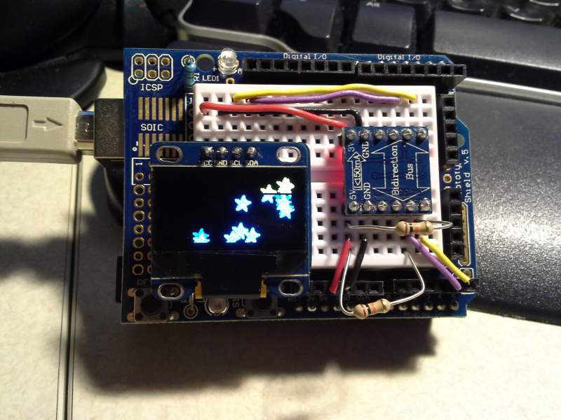
04/08/2015 at 18:17 • 0 commentsOver lunch today I finished hooking up one of the OLED displays to the breadboard shield on my Arduino Uno. While the OLED is supposed to be tolerant of being powered and communicated to with 5v, I've read a few forum posts that seem to indicate that it could be unreliable. I happened to have a bidirectional 3.3V level converter (although from what I understand, the OLED I'm using often only receives and doesn't transmit), so I used that to hook it up.
I first tried with the u8glib library, but their example code (using the No Acknowledge setting) caused nothing to happen on the display. I then followed what this guy did:
His example uses the Adafruit library. I, too, had to change the I2C address to 0x3C for mine. After that, though, it worked (well, after figuring out that my connections were off by one on the level converter).
The example is pretty big, though. It takes about 20k (out of 32k) of flash and 1580 bytes (out of 2048) of RAM. I don't know if I can leave out certain parts of the library that I don't need or maybe the example code uses quite a bit more memory than my code will use.![]()
I may try the u8glib library again now that I know my setup works to see how much memory it takes.
I added pullup resistors to the 5v side of the I2C lines. It worked fine without them (maybe because of the level converter), but I added them just to be sure.
-
Cruise control switch
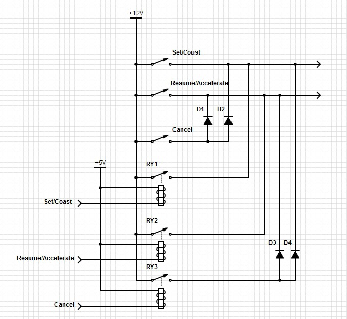
04/01/2015 at 22:18 • 0 commentsThe existing cruise switch is wired as shown in the top half of the schematic below. Diodes are used along with the switches to send 3 inputs over two wires. I plan to replicate that setup using relays that will be controlled by my project. This is shown in the lower half the schematic. I can't think of a use for the cancel control for my project, although I may include the connections since it will be easier to do now than to add later.
![]()
Cruise Control Preset
This project supplements the existing cruise control in a vehicle, allowing you to automatically set the cruise control to a selected speed.