The time has come to put electrical and mechanical (and some emotional) parts together! A friend of mine that made his own 3D printer helped me with the mechanical parts (thanks once again Martijn Sanderse!).
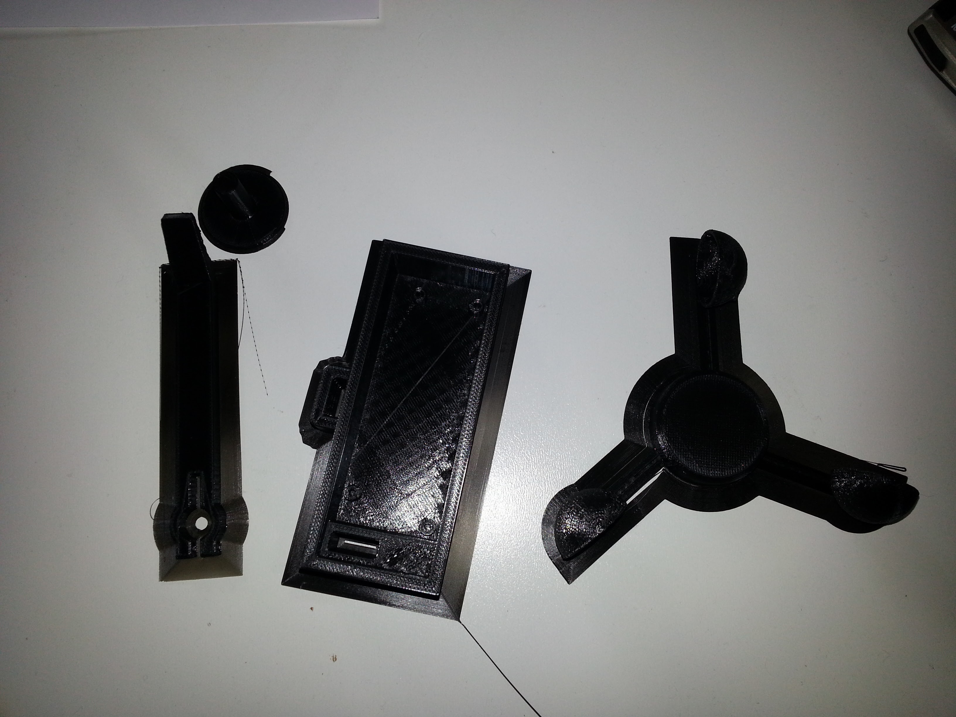
As a first step however, I needed to extract the parts I needed for the anemometer. I'm using a small DC computer fan for this purpose.
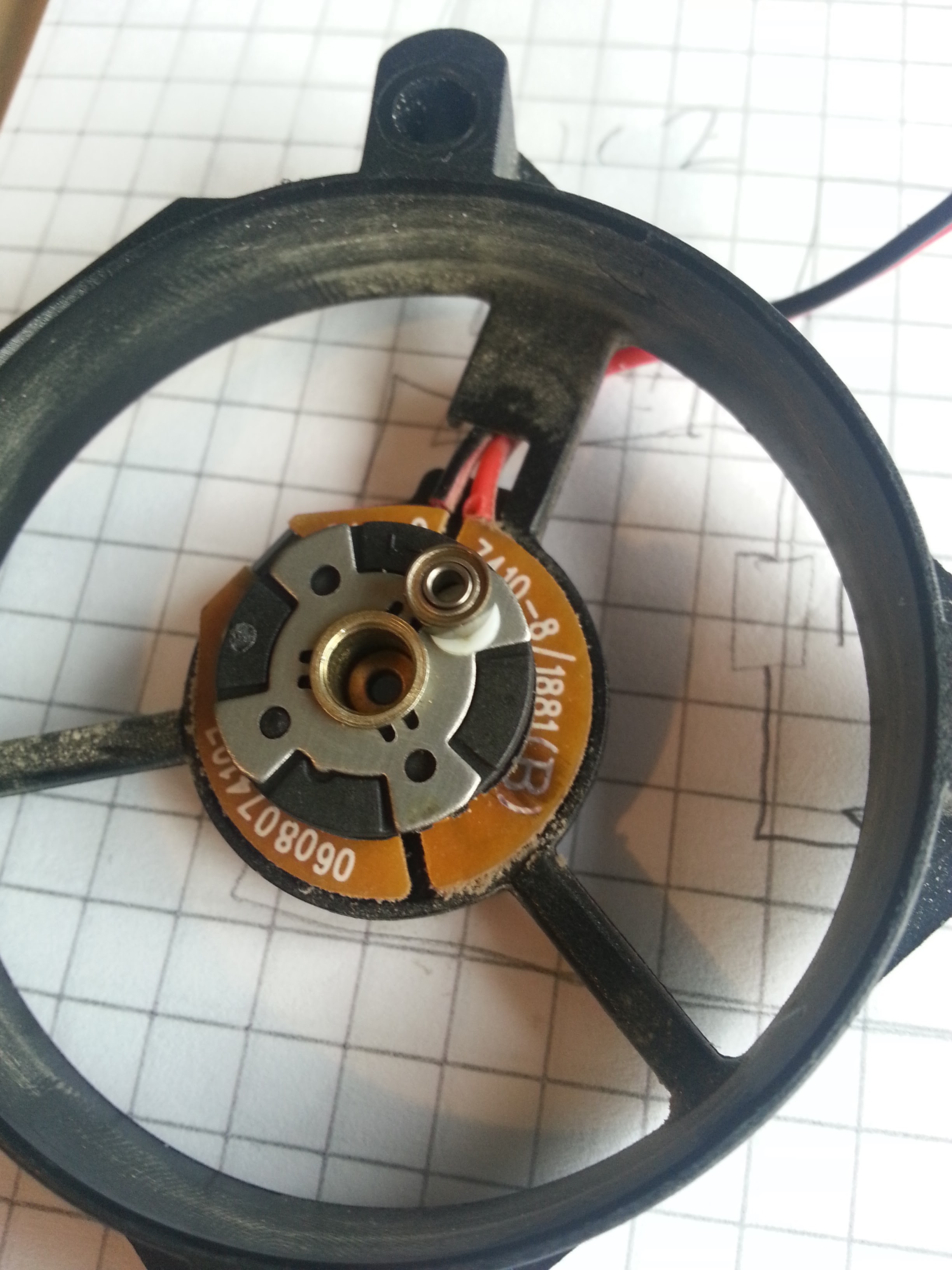
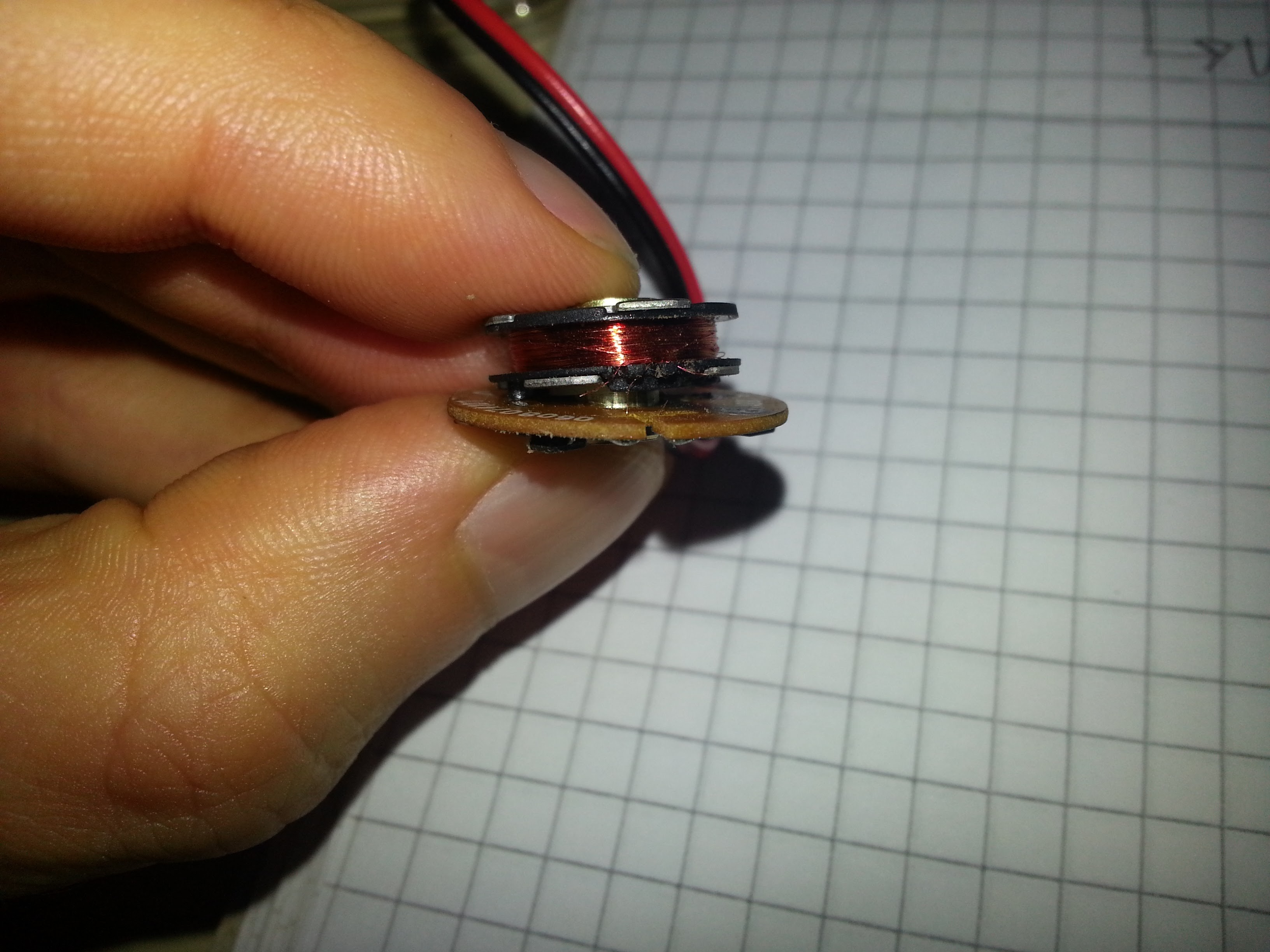
As seen above, I managed to get it open, but in the process I ripped the tiny coil wires (DOH! see picture below). For the first prototype, I will only use the hall sensor, in other words.... (ie, not using any wind energy)
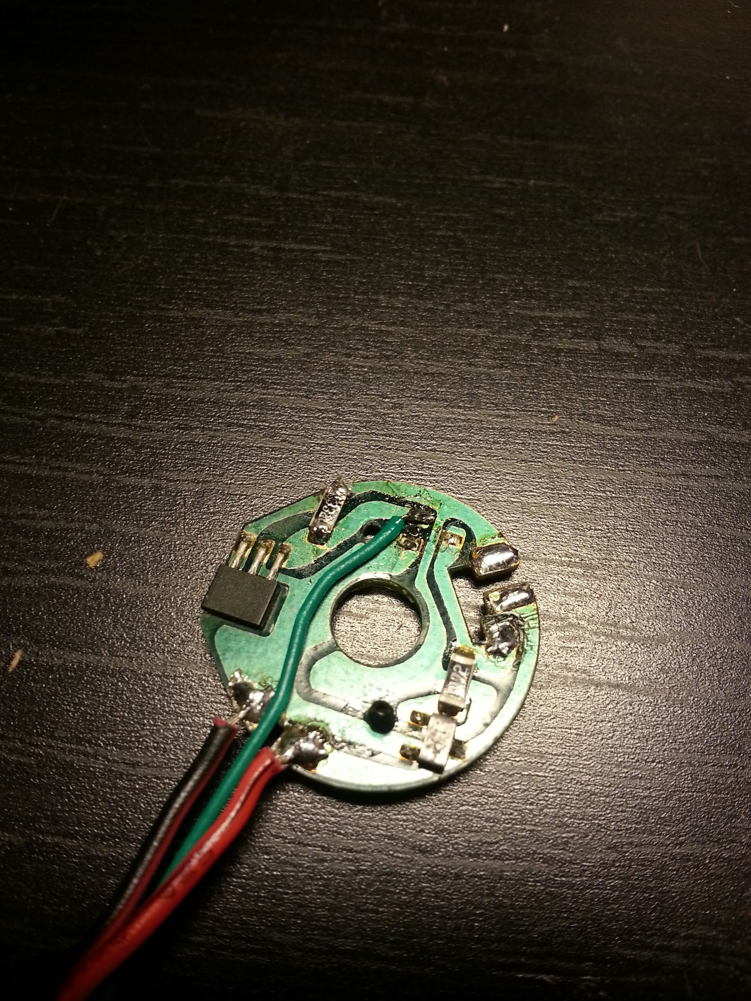
The hall sensor is the largest IC in the picture below. In fact, I had another, slightly larger fan in mind to start with, but it turned out that the hall sensor on that fan needed amplifier and hysteresis circuitry. This one only needs VCC and a pull-up resistor on the output. In the picture you can see that I have added a wire for the output and removed one component (I believe is was a diode).
Next, the fan parts need to be fitted on the 3D printed structures. I cut the wings on the part in the bottom left, and attached it inside the anemometer. The bottom right part, with the wires, I glued on the holder seen on the top right (on the side which is down in the picture).

And here we have all the parts together, including the solar panel!
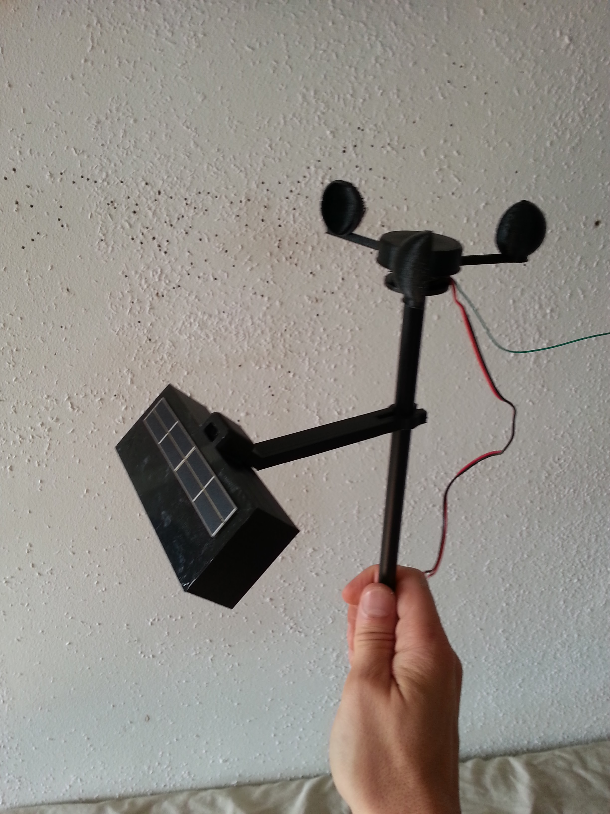
Stay tuned! In the next post I will publish a short video, showing the prototype in action.
 Ulf Winberg
Discussions
Become a Hackaday.io Member
Create an account to leave a comment. Already have an account? Log In.
[this comment has been deleted]
Thanks!
Are you sure? yes | no