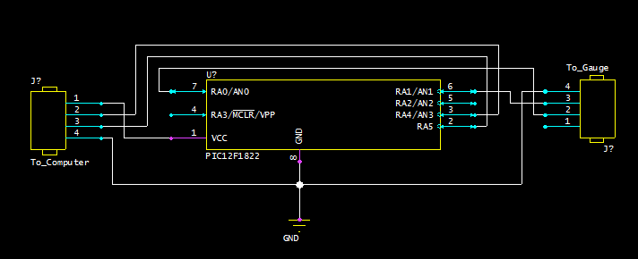
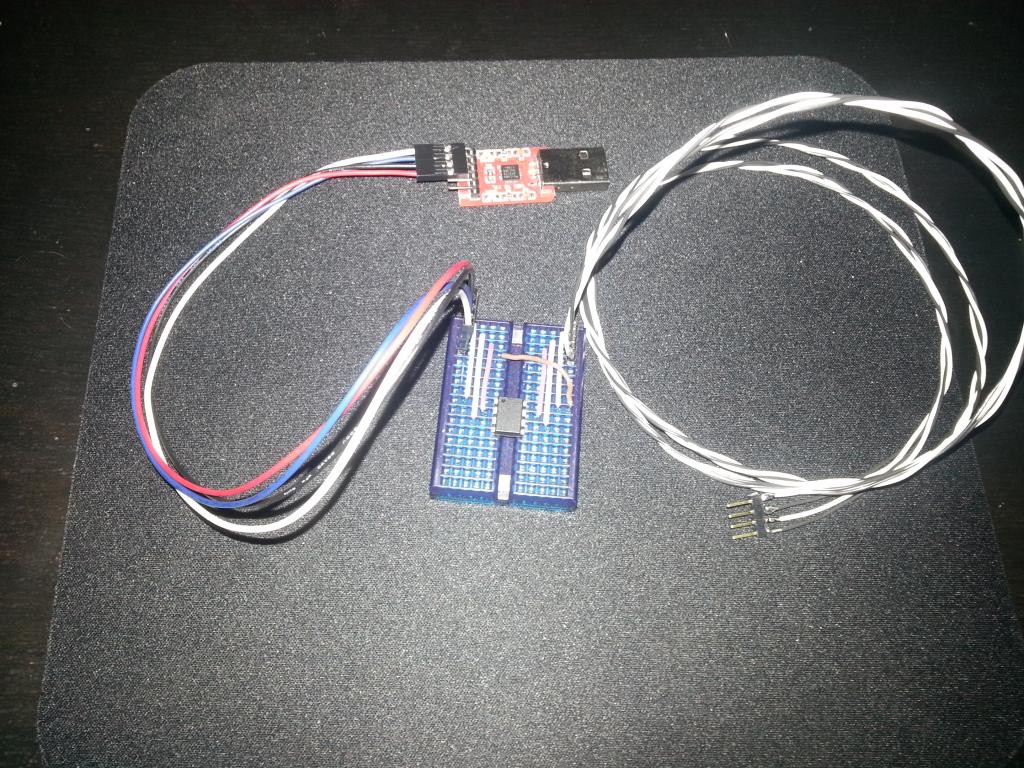
Here is the very simple circuit I am using for the PIC chip which converts unique protocol from the dial indicator to regular UART signals that can be read by a USB TTL adapter (serial protocol @ 5V).

This will probably the first circuit I try making once I get to that point. For now I'm just using small breadboard.

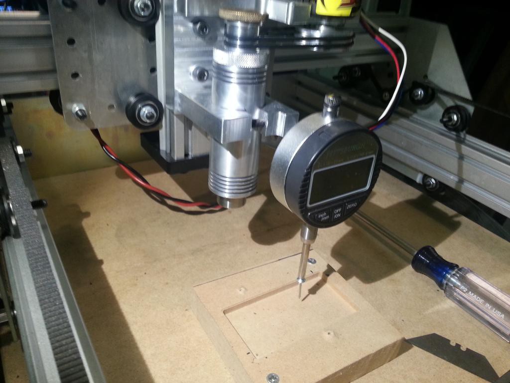
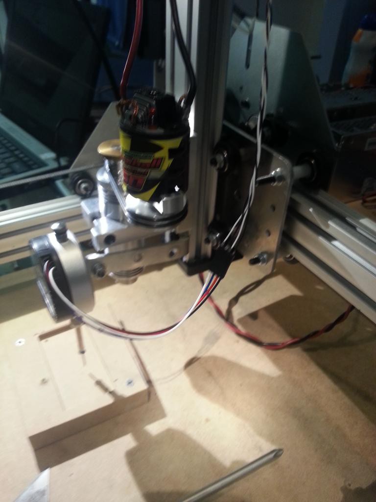
I have also mounted the dial indicator to the CNC machine.


Now that the dial indicator is mounted and we can read in its values from the computer, its time to make a program to use the data. Eventually this program will take in this data, create a surface map and then alter a g-code file by offsetting the Z values to match the interpolated surface map. But for a first step, I have made a program in python that will probe around in a grid and generate a surface and then displays that surface map on the screen, updating it for each point. The interpolation and altering the g-code will be added in the future. I'll post all the code once it is more or less finalized.
Here's a video program and probe in action:
 Justin R.
Discussions
Become a Hackaday.io Member
Create an account to leave a comment. Already have an account? Log In.