Ok we need some way to detect how many rotations the shaft makes, a CPU board, and a Real Time Clock (RTC). We should have some Flash memory as well to store our data points.
Photo-Interruptor Circuit
An easy way of detecting shaft rotation is by using a photo interruptor circuit, cost £0.99.
It works by having a LED (light emitting diode, usually infrared), and an opto-transistor. The transistor conducts depending on how much light falls on it, coming from the LED.
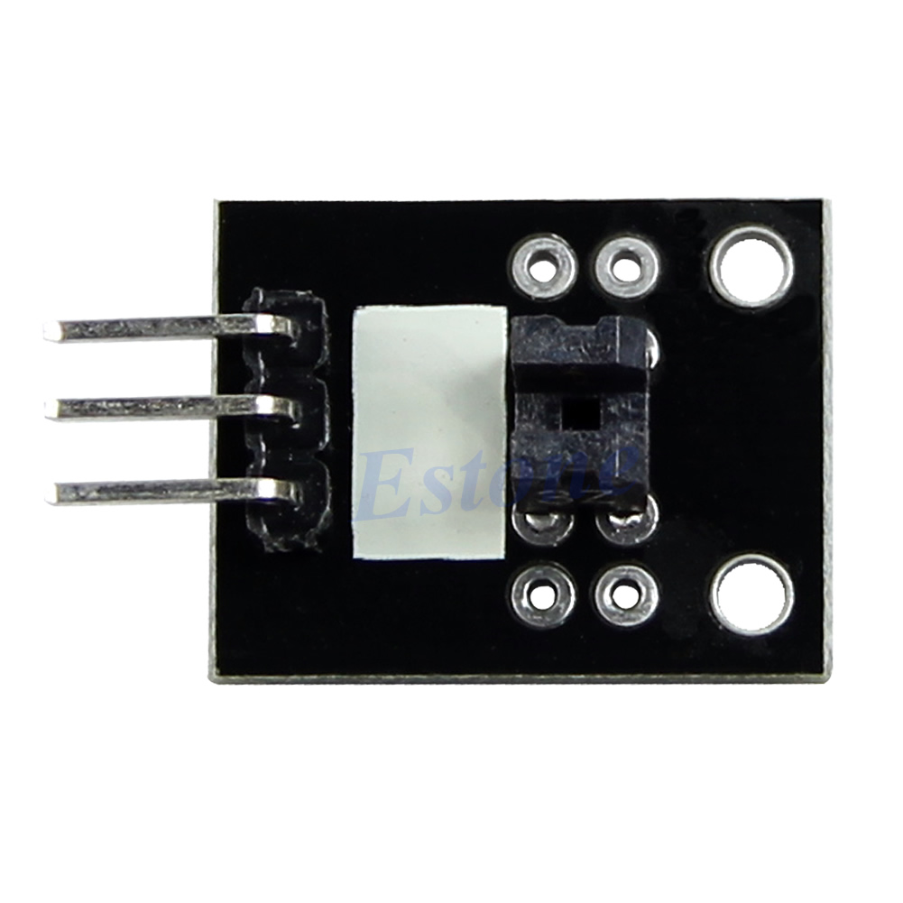
By inserting something in the slit between the LED and the opto-transistor, the output changes. I have no idea what type of transistor they put on this PCB, so assume it's just a simple transistor, without any schmitt-trigger capability. It doesn't matter in the end anyway. It'll work whatever is sent (famous last words...).
Processor Dev Board
Usually with low power requirements, I would grab an MSP430 processor, because they are usually the least power hungry processors around. However, finding a cheap dev board is expensive :(
Basically, I'd like to choose something cheap & simple & easy to obtain, so people can copy this project.
In the end I came up with Arduino. I've never used it before, so let's plunge into the deep.
A mini Arduino board (£2.24), which looks pretty, but has no programmer.
 |  |  |
I also came across this one that seems to have a programmer already, or this one.
I must admit that I've bought the three mentioned dev boards, just so I can have a look at how well they perform. £2 for a dev board is a good price I must say.
The ATmega328P (large PDF!!) on this development board provides the following features:
- - 4K/8Kbytes of In-System Programmable Flash with Read-While-Write capabilities,
- 256/512/512/1Kbytes EEPROM,
- 512/1K/1K/2KbytesSRAM,
- 23 general purpose I/O lines,
- 32 general purpose working registers,
- three flexible Timer/Counters with compare modes,
- internal and external interrupts,
- a serial programmable USART,
- a byte-oriented 2-wire Serial Interface,
- an SPI serial port,
- a 6-channel 10-bit ADC (8 channels in TQFP and QFN/MLF packages),
- a programmable Watchdog Timer with internal Oscillator,
- and five software selectable power saving modes;
- - The Idle mode stops the CPU while allowing the SRAM, Timer/Counters, USART, 2-wire Serial Interface, SPI port, and interrupt system to continue functioning.
- - The Power-down mode saves the register contents but freezes the Oscillator, disabling all other chip functions until the next interrupt or hardware reset.
- - In Power-save mode, the asynchronous timer continues to run, allowing the user to maintain a timer base while the rest of the device is sleeping.
- - The ADC Noise Reduction mode stops the CPU and all I/O modules except asynchronous timer andADC, to minimize switching noise during ADC conversions.
- - In Standby mode, the crystal/resonator Oscillator is running while the rest of the device is sleeping. This allows very fast start-up combined with low power consumption
Power Consumption at 1MHz, 1.8V, 25C
- Active Mode: 0.2mA
- Power-down Mode: 0.1µA
- Power-save Mode: 0.75µA (Including 32kHz RTC)
And look, active mode 0.2 mA. Far below what I guestimated for current use (1 mA). The batteries are going to be fine!
Sorry for the large amount of text, but all in all, this processor has got everything that we need; EEPROM to store our desired strut lengths, an ADC for measuring the photo-isolator, plenty of output pins, low power, and an RTC. Hmm Atmel says it has an RTC, but what they call RTC is not a Real Time Clock, but a Real Time Counter. Not sure if that'll work. We will see.
Anyway, I've ordered all the required components, now I have to wait for a few weeks for them to arrive :S.
Discussions
Become a Hackaday.io Member
Create an account to leave a comment. Already have an account? Log In.