 Benchoff
Since I'm waiting two weeks or something until I get some boards and parts, It's a good enough time to figure out how this thing is going to be programmed. The first step to that is documenting how I laid this thing out. Here's the pin map:
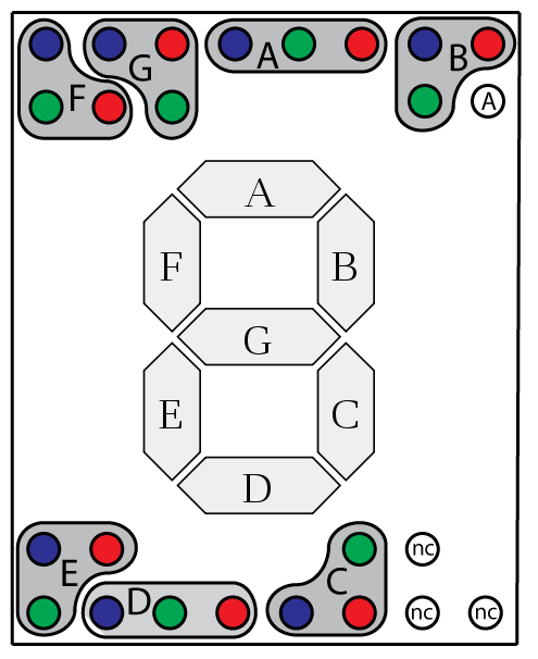
Now it's a matter of how to connect this to the driver. Here's the datasheet for the driver. It gives me eight RGB drivers. Here's a table, because the editing tools on here are awesome:
| How the displays are connected | |
| Driver output number | Segment of the display |
| 1 | B |
| 2 | A |
| 3 | G |
| 4 | F |
| 5 | E |
| 6 | D |
| 7 | C |
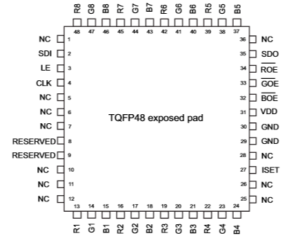
And the pinout:

Discussions
Become a Hackaday.io Member
Create an account to leave a comment. Already have an account? Log In.