 PCB designer
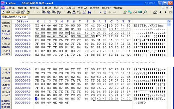
2.1.1 Digital Audio Basics
The basic principles and methods of digital audio processing technology is to use ADC, the analog digital converter, to take sample, quantize, encode and convert the analog audio signal into digital data and files to be saved. Of course, during the playback, the digital data goes through the DAC digital analog converter to restore the analogy signal form to be played out by the sound device.
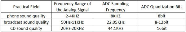
Depending on the application range of the audio signal, the sampling frequency and the quantization accuracy of the analog audio digital 0ADC varies. The following table shows the common standard:
As you can see from the above table, according to the sampling theorem, for audio signal with different qualities, the digital audio ADC sampling frequency is twice the highest frequency analog signal. Additionally, the higher sound quality you require, the higher ADC quantization bits. In fact, the human ear cannot tell 1/256 level (8) precision changes, but for the CD sound quality, we use 16 quantization bits, precision 1/65536. Apparently, the better sound quality a digital audio has, the greater the amount of data it has to deal with. As for a second audio signal, when it's a telephone-level quality digital audio, the amount of data is 8k bytes with each byte stored the level value of one sampling point. To obtain a CD-level quality digital audio, the data amount for every second is 88.2k; that amount is 176.4k for a two-channel stereo.
The most typical digital audio data file is WAV, which is mostly by using the original PCM encoding to store the raw data for each sampling point. Without any compression, now we got a sound card(either integrated or stand-alone) with build-in microphone port, under the support of WINDOWS platform, we can record, that is, turn the sound into digital audio and save it in the computer. And this file we saved, is WAV format file. Therefore, when we follow the sampling frequency speed to read the audio data one by one, the file is converted to analog signal by DAC, thus, the sound can be represented.
2.1.2 WAVE Format Introduction
WAVE format (extension: wav) is one of the basic audio formats used in multimedia digital audio, which is based on RIFF format as a standard. RIFF is short for Resource Interchange File Format. The first four bytes of each WAVE file is "RIFF".
WAVE files are composed of several chunks (blocks). According to their positions in the file, they are: RIFF WAVE chunk, format chunk, fact chunk (optional), data chunk, LIST chunk (optional), etc. Of all listed above, except for RIFF WAVE chunk, format chunk, data chunk, the others are optional.
2.1.3 Get PCM Audio Data from WAV Files
There are many WAV format files in PC. In fact, all prompt tone WINDOWS uses WAV format files. We can certainly create whatever audio file we need with the software on the PC. In the materials we provide a WAV file "talking microcontroller.wav" for readers. You can use the software WINHEX to view the specific content of the file in binary format (displayed as hexadecimal). The picture below tells how to display the content of the file by using INHEX.
According to the previous introduction of the WAV format audio file, you can find out the audio data part. The chunks have been marked in the following picture, and the parameters have been listed.
2.2 PWM2.2.1 Introduction
PWM, is abbreviation form for "Pulse Width Modulation". It is actually a
very effective technology in the field of using microprocessor to control the analog circuitry, widely used in measurement, communication, power control and conversion and many other fields.
2.2.2 PWM Generation
The most common function of the microcontroller is timing. It's a simple
internal timer, when incrementing to a certain value, it returns to zero. PWM generates from these timers, outputs high level via the external pin. When the timer reaches zero and the output low level reaches another value, you can invert the two values. By this method, you can make the output pin remain at a high level within a particular time length, instead of switching its codes manually. If you output pin through a low-pass filter, you can get the average.
2.2.3 ADC Function Realization
The resistor R and the capacitor C on the PWM output pins simply constitute an integrator circuit. When filtering out high frequency to obtain smoothing, you can get the analog audio output at the audio output. Here, based on the example we provide, for a wav file, since the PWM frequency generated is 8 kHz, the PWM output signals contains many high-frequency signal components: greater than 8k. Therefore, the cutoff frequency of the low-pass filter composed of the resistor R and the capacitor C should be around 6 kHz so as to filter out signals with high frequency of over 8k, only to retain the analog signals with frequency under 4 kHz.
The cutoff frequency of the low-pass filter composed of the resistor and
the capacitor is calculated by the formula: F=1/2∏RC. Introducing the numbers, here's what we get: 1/(2*3.1415*2700*0.00000001)=5897.6Hz. Thus, when R=2.7k, C=0.01uF, the cutoff frequency of the filter is approximately 5.9 kHz.
Discussions
Become a Hackaday.io Member
Create an account to leave a comment. Already have an account? Log In.