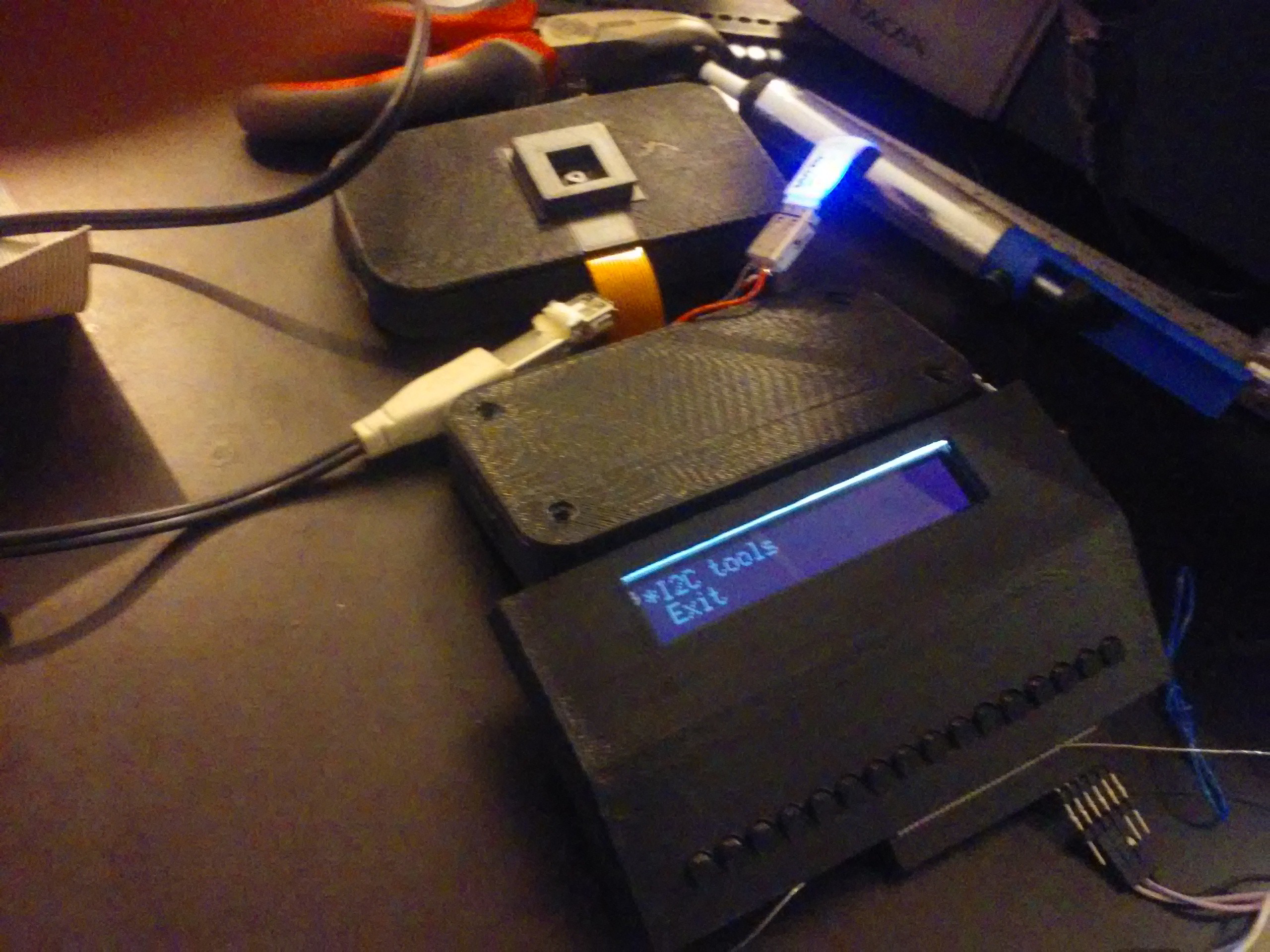
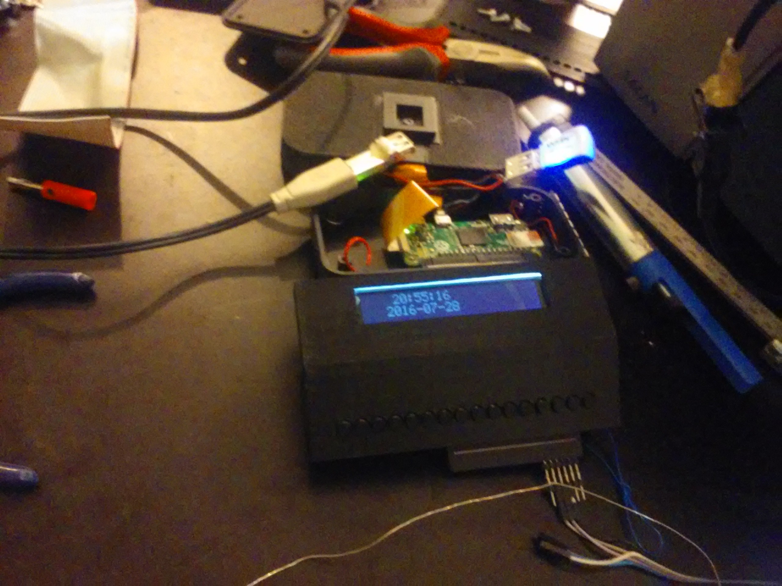
I didn't have time for this project for quite some time. However, after I've finished work on some other projects that had higher priority, I decided it's time I finish this project. Let's do a writeup on how it looks now:

So, first thing to come is 3D-printed parts. inb4 - just updated the files for download.
Modules

Main module (with the Pi board) got completely redesigned. Now there's a Pi Zero in there. I can still use the native camera with the adapter cable, CPU power is the same (I was planning to use a B+ anyway) and power consumption will probably be less than the B+'s (though a USB hub I'll add might just compensate for this). It's got a 3D-printed case which dimensions make this the smallest module, and I could make it even smaller. Some features:
- Screw holes. The case lid is snap-on, but I've decided to add some screws, so it's now held by 4 nice M3 HEX screws (ones you'd need an Allen key for). I should probably color them black though, or just get black screws.
- WS2812 header. I got a "Neopixel Stick" knockoff from eBay and added a header from those. Now the flashlight is included in the CPU module. It's a little unsightly, but I plan to design a small piece which'd cover it.
- Accelerometer and gyroscope - with MPU-6050. I plan to add a magnetometer as well. I still need to connect them to I2C though, they're not connected right now.
- An external USB port.
- Later on, soundcard and a 3.5mm socket for headphones. It seems I'll make a hole for the headphones with a dremel, since the first version of the case has already been printed.
- A RTC for good measure
A IDE cable connects Pi's GPIO straight to the display module.
- A RX2402A display from TME.eu I got from a hackathon.
- A custom board with 16 keys and an I2C expander
Then, it goes to the power module:
- A HAT connector (I still might want to use some HATs without dismantling the whole setup)
- 2 GPIO connectors (IDE-style) - one goes to the display module, one goes to the communications module (they're not connected on board but instead have SMD pads broken out, it's so that I can choose which lines are connected both to the second connector and to the HAT connector)
- A RC522 card reader
- Possibly, some DC-DC modules for powering everything from Li-ion directly - when I finally get to this part.
- USB sockets for powering things
From the power module, another cable goes to the communications module:
- A Pi Camera connected to the main module's Pi
- A USB hub, connected to the Pi as well
- One USB socket accessible for flash drives etc.
- BT 4.0 dongle
- WiFi board
- Later on, an Arduino which would switch power to WiFi/BT/USB hub/soundcard/etc. using a small board with FETs
What's lacking now?
- GPS. I have a module right now, might just find some free place for it in the communication module.
- GSM. Ditto, another small module waiting for inclusion ASAP. I want a DIY phone, dammit!
- Sound card. One of the most urgent things, actually, since listening to music on the go is one of the most important things for this to do.
- Keypad glove. I've recently received a ton of buttons from China, but I'm still confused over how exactly I'd connect them. Will need to think about feasible ways - I'll probably choose a spare Pro Micro over USB though.
- Battery management. I haven't yet thought of where I'd be carrying batteries, much less about their management. I'll probably whip up something when it's time.
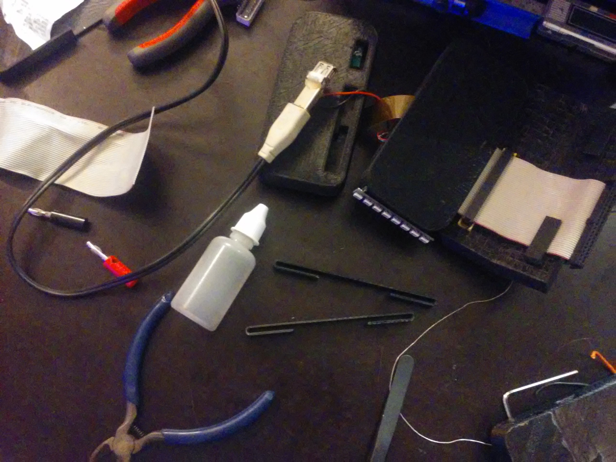
- Some kind of belt clips attached to the back of all modules so that the case can be held together by the belt that wraps around the wrist. It's now held by the IDE cable but this is not enough.
Some simple belt clips - to be glued to the back of each module so that I can attach belts:

See you soon with updates, hopefully.
 Arya
Arya
Discussions
Become a Hackaday.io Member
Create an account to leave a comment. Already have an account? Log In.