 techav
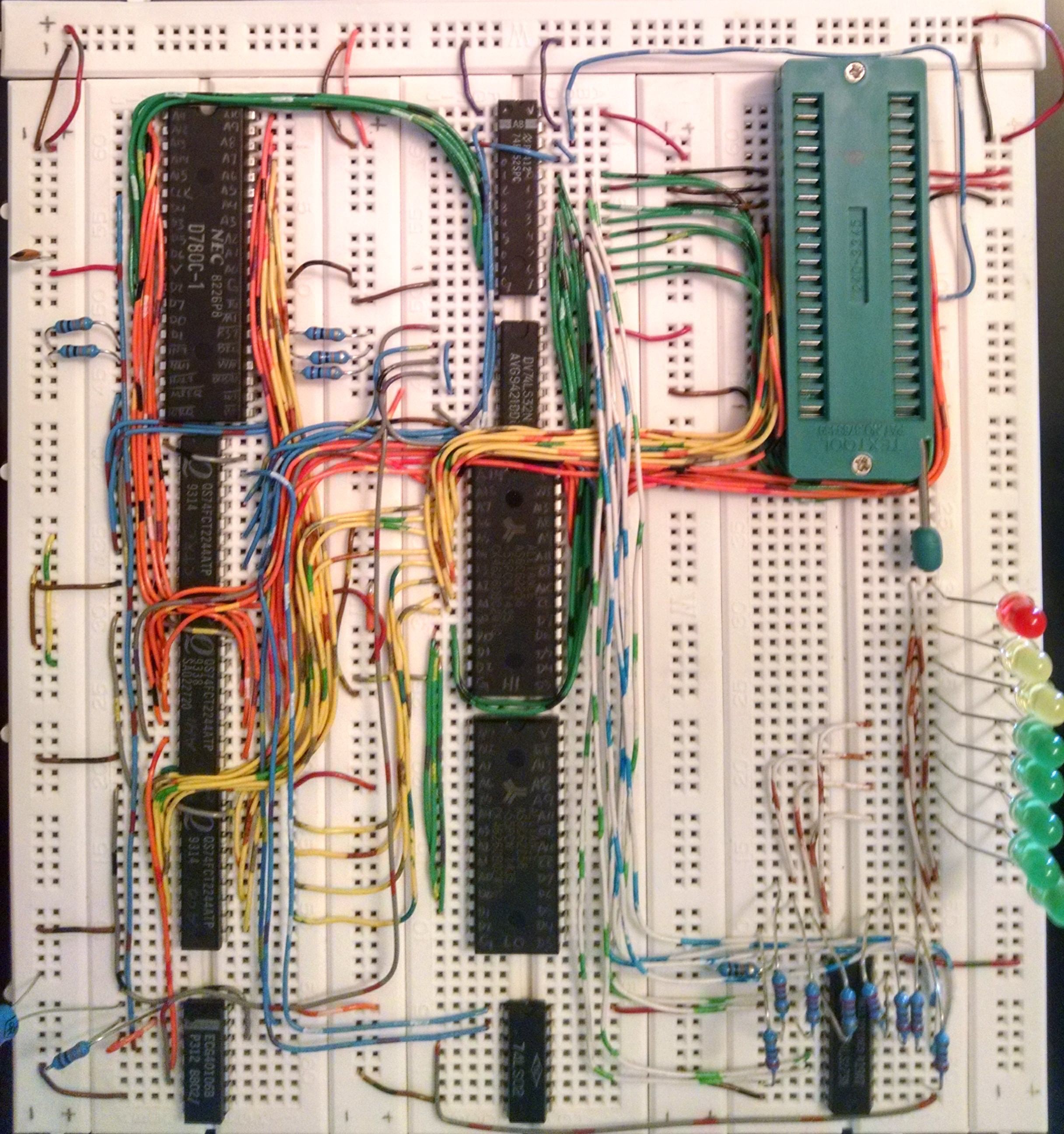
I spent a few hours last night wiring up my breadboard. I'm using three 74x244 buffers for the address bus and control signals, a '652 transceiver for the data bus, a '32 quad OR for some glue logic, and a '273 register for output. My Flash is serving as ROM on the low addresses, and an SRAM on the high addresses. The second RAM chip is on the board, but not wired in yet. Eventually I plan on being able to bank swap ROM for RAM in the low addresses. Clock is provided by an oscillator built from a 40106b hex Schmitt trigger inverter.
My first test program is a simple as could be. 0x01 is loaded in to register A, then a loop of output A, rotate A.
ASM and Hex compiled by zasm:
            org    0
            LD     A,1H
myLoop:     OUT    0h,A
            RLC    A
            JP     myLoop
:090000003E01D300CB07C302004E
:00000001FF
The clock of the '273 is tied to the OR of /IOREQ and /WR, so it latches on every OUT instruction. The result is LEDs 0-7 lighting up one-by-one then starting over with LED 0.
I can't believe it actually works ...
Discussions
Become a Hackaday.io Member
Create an account to leave a comment. Already have an account? Log In.
Impressive! Reminds me of the time I had to breadboard an ATmel ARM7TDMI chip that was on a PCB breakout. I wanna do the same thing with a 6502 I found. Rock on!
Are you sure? yes | no
nice! And on a breadboard!
Are you sure? yes | no