While fuzzing with the PCB layout, I also thought bit about the form factor, especially if the dongle-style I was going for is really good solution. While it is pretty neat to have it in a compact package that you can just stick in (like those modern 3G/4G USB modems) without needing to have cables and such, there are several downsides too. One of the biggest problems what I hadn't been thinking originally is the need for external power. A battery is not going to fit into a dongle form factor, no matter what. Another 200LX specific issue is that the "ground clearance" for the serial port is not very great, maybe less than 5mm. My board designs are loaded on both sides (to get the small size), so while I think they'll still fit, it will be pretty tight and designing any sort enclosure will be a challenge. More generic problem is that dongles are kinda fragile and might end up damaging the host port if knocked off because they are all rigid and sticking out in a perilous way. Finally even a reasonably small dongle will feel pretty big when sticking out from 200LX, just because the device itself is so much smaller in comparison to typical laptop which such dongle might be attached to.
So what I'm going to do? Not sure at this point. One idea I had was that I could form a wire mounting clip and hang the module with it on the screen bezel at the back side. It would not address the battery issue at all, but could be otherwise kinda neat way make the whole setup more mobile.
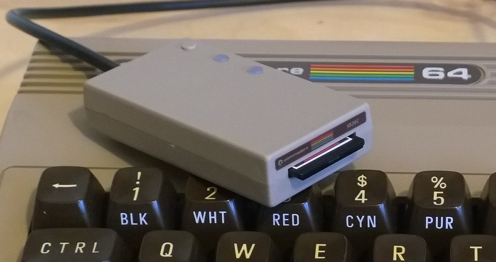
Another more obvious idea is just to put the module in a external box. I could then fit a small lipo cell in there too, so that would solve my battery problems. The also obvious downside being that I'll lose a lot of portability if I have handle a separate box around. On the other hand, external modems are very retro and I could design a fancy custom 3D-printed enclosure that both evokes old classic modems and matches the 200LX design, kinda same way like some of the adorable SD-card floppy disk emulators I've seen:

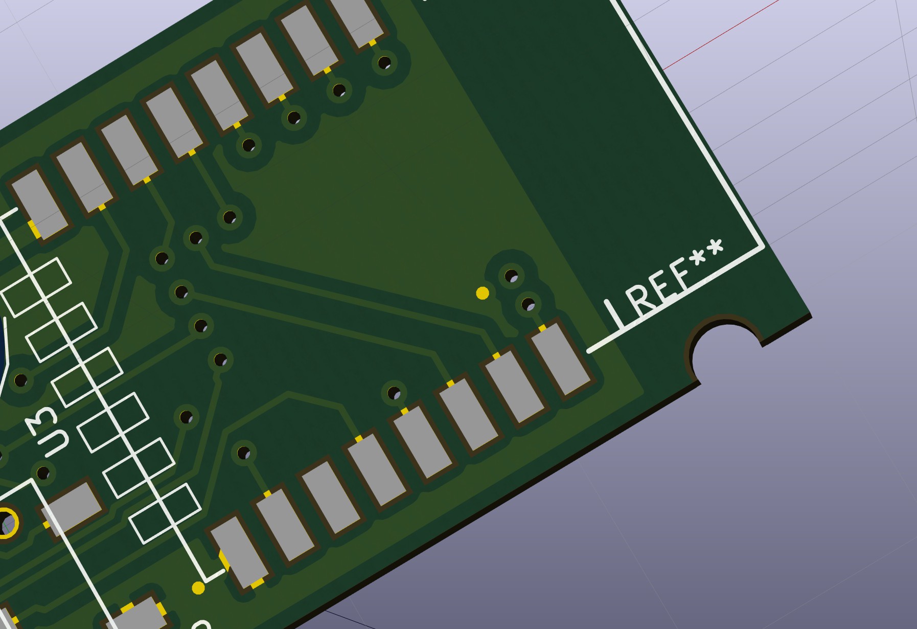
While all this pondering does not necessarily affect the PCB design all that much, one thing I do need to decide is what sort of mounting holes (if any) I will be adding. For a bare dongle there isn't really need for those, and as such I hadn't planned for them either (whoops..). But if I want to make any sort of enclosure then I most likely will need some holes. Problem being of course that the board currently doesn't really have all that much extra space as such, and I'm not sure if PCB fabs are happy with this sort of things:

I'll have to check if that is ok. For reference, that's 2.7mm hole from KiCAD library for M2.5 screw, which is pretty much the only thing that possibly could fit in (I guess?).
Of course I could redesign the whole board for specifically enclosure in mind, that would probably allow me to make the board bit bigger (if the battery sits on top of the board), and that way I might be able to do it in 2 layers (current design is for 4 layers, which is slightly extravagant) and single-sided assembly which would make life easier.
Discussions
Become a Hackaday.io Member
Create an account to leave a comment. Already have an account? Log In.