 Capt. Flatus O'Flaherty ☠
Not all tests go to plan and this is one of those cases - a leek plant was destroyed :(
The objective of the test was to look at how well the 35 kHz wire guided the machine with 10mH inductor sensors, and whilst this seemed to be very successful, the velocity of the recently upgraded motors could not be controlled precisely enough for successful X axis navigation. The motors need enough voltage to overcome 'stiction' but then, once the machine is moving, the voltage needs to be reduced to keep the speed nice and slow.
A rotary encoder needs to be incorporated into the design and the drawing below shows my proposed solution which also solves the problem of regulating the height of the encoder bar. This was thought to be easier than trying to retro-fit the encoder into the wheel drive gearbox and has the advantage that there won't be any problem with backlash and there will be more accuracy due to the smaller size of the wheel.
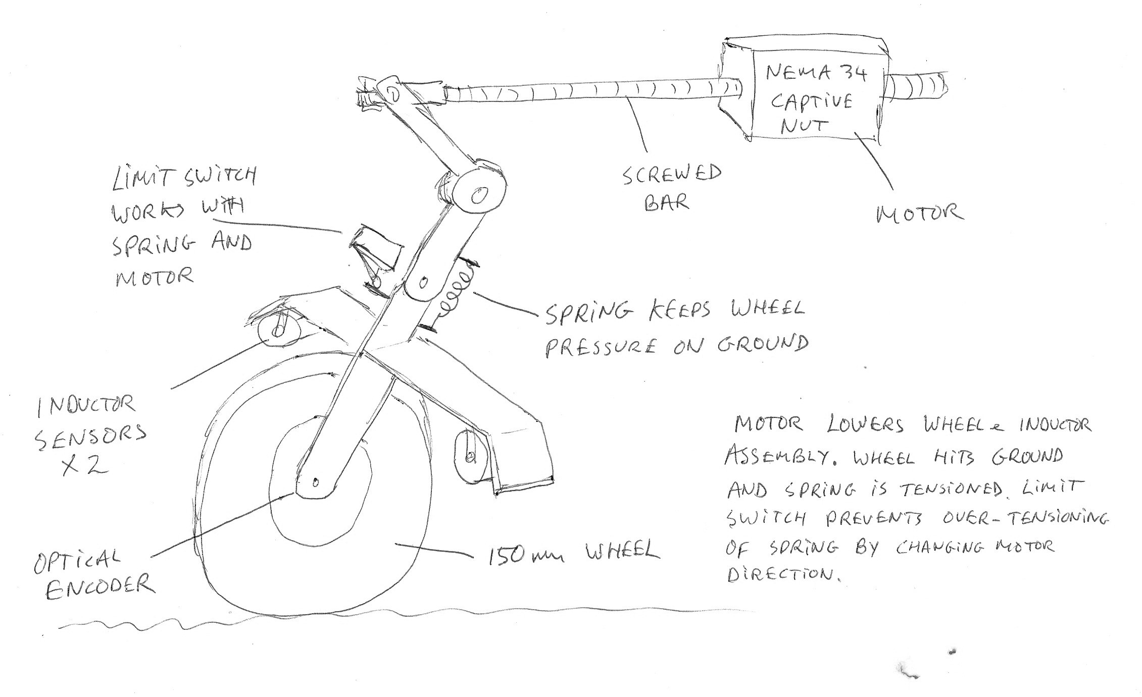 I've got a spare NEMA 34 captive motor lying around in the workshop which acts on a pivot lowering and raising the rest of the assembly. A second pivot a bit lower down enables the wheel to be pressed with constant pressure down onto the ground, with the limit switch constantly changing the direction of the motor whilst the system is in use. If the wheel hits an obstacle such as a stone, the main spring absorbs the extra travel, as does the springy limit switch lever. Another solution would be to put a strain gauge sensor on the spring, but I think this would be over complicated - better to just expend a few watts in the motor.
Discussions
Become a Hackaday.io Member
Create an account to leave a comment. Already have an account? Log In.