 ACROBOTIC Industries
With some of the parts in hand, the first thing we need is to connect the ESP-01 and the 8-bit NeoPixel LED board. Given the goal of a minimalist design, we choose to mount the two boards back to back. Conveniently, the spacing of the pins and pads is the same (0.1" pitch) so they physically line up. So let's consider now the pinout of the two:
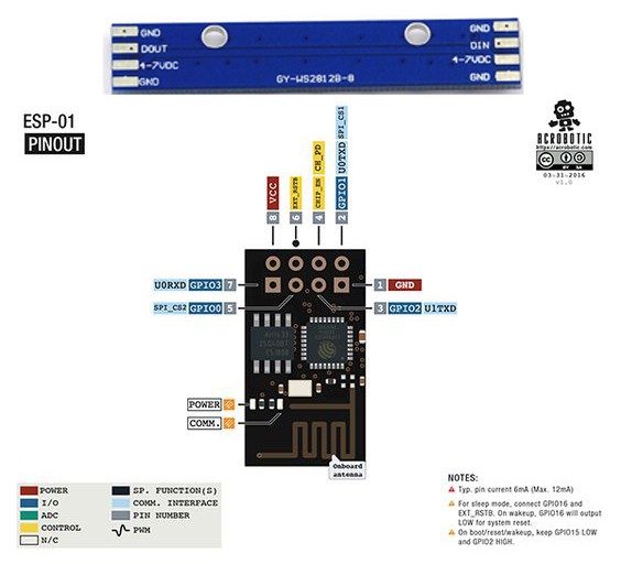
Just for kicks and giggles we'll remove the pin header from the ESP-01, and use 3 pins from its top row to connect to the LED board so that the connections are as follows:
ESP-01 | LED board
GND-----GND
GPIO2--4-7VDC
GPIO0--DIN
This is not a great idea because we plan on using GPIO2 to power the LED board even though it won't provide neither enough voltage (3.3VDC max) nor source enough current (50~60mA max). ¯\_(ツ)_/¯
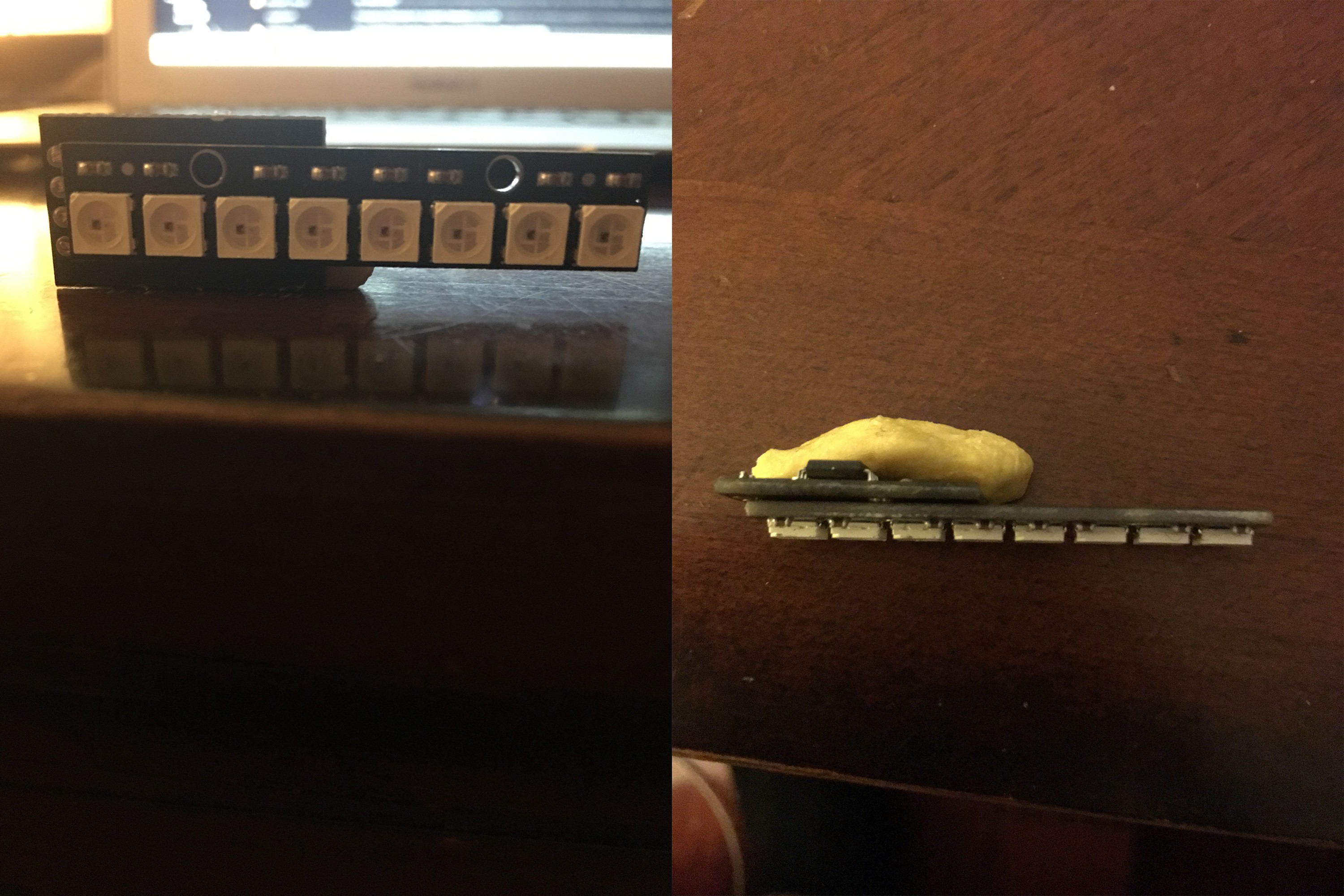
To avoid any interference from the second GND pad on the LED board, and the pin with which it lines up on the ESP-01 (U0RXD or Rx), we remove the pad by applying a bit of heat with the soldering iron.
After soldering the two together this is what we have:
Now we move on to building a little programmer to load our test code!
Discussions
Become a Hackaday.io Member
Create an account to leave a comment. Already have an account? Log In.