 Hari Wiguna
// Simple KnightRider pattern to test 8 IO pins driven by the ESP-12 using Arduino IDE for ESP

// Wiring notes:
// CH_PD and RESET must be connected to 3V3.
// GPIO15 must be connected to GND.
// GPIO0 must be connected to GND prior to uploading sketch, but otherwise can be used freely

byte pattern[] = {4,5,0,2, 16,14,12,13, 12,14,16, 2,0,5};
int pinIndex = 13;

void setup() {
  byte pins[] = {4,5,0,2, 16,14,12,13};
  for (byte i=0; i<8; i++) {
    pinMode( pins[i], OUTPUT);
  }
}

// the loop function runs over and over again forever
void loop() {
  digitalWrite( pattern[pinIndex--], HIGH); // Off
  if (pinIndex==-1) pinIndex=13;
  digitalWrite( pattern[pinIndex], LOW); // ON
  delay(100);
}
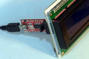
To learn how to start writing Sketches for the ESP8266 using the Arduino IDE, see Arduino IDE for ESP Quickstart Guide


 InvIoT Dimitri Synodinos
 Mishel George
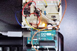
 Gustavo Reynaga
 electronicsworkshops
Hey there! Finally found this again. Can't you use a pull-down on GPIO15 to use it as well? I'm finally getting a project started with the ESP modules and was looking for this project - thanks for sharing!