Close
0%
0%

Share the Warmth

Warm-air distribution system (PIC/JALv2)

Similar projects worth following
Background:
We have a wood stove and it is fabulous. It's made from cast iron and soapstone, so it heats up very slowly, but once it's going it burns 24/7 and provides not just a source of heat, but also a centre-piece and focal point within the living area. It is clean burning and will happily stay alive through those long winter nights on just one load of wood, with the soapstone still radiating heat in the morning.

The Problem:
Although we have an open-plan living-dining-kitchen area, the bedrooms and bathroom/toilet are on the north side of the house and, because there's no natural airflow from the lounge area, they get exceedingly chilly at night (we're at 700-metres). We really need an additional heat source for those back rooms.

The Solution:
The wood stove works well, so all we really need to do is channel some of that heat into those rooms. It doesn't have to be tropical in there, just warm enough so that it's not torture getting out of bed in the morning.

Okay, I cheated (just a little bit). Even before we built the house, we could see that this was going to be an issue, so when I was panelling the internal walls I left spaces for ducts to run from the lounge area, through the under-stairs storage area, to strategically placed openings in the walls of the "cold" rooms. The plan was to use forced air from the "warm" lounge area to provide warmth from the woodstove.

The Cheek of it:

Yes, I admit it ...I'm submitting to the 2015 Hackaday Prize simply because I could do with an upgrade from my multiple, 40-year old~H~H~H~H~H perf/stripboards to a nice, clean, purple PCB.

Environmentally friendly? Yup, tick that box ...even though the environment in question is limited to our bedroom and the bog. Seriously though, this project does save us from installing another form of heating, so it reduces our carbon footprint just a little. It's difficult to envisage this being applicable elsewhere, though.

The Hardware:

The hardware is very basic. I'm using 200mm, 700RPM, 12v fans to move the warm air through the ducting. Because they run so slowly, they are also fairly quiet, at just 19db. The fans are slowed down even further by using a PIC18F27J53 microcontroller to provide PWM drive to what is effectively a very simple switching (Buck) regulator from a 21v supply. Why 21v? Because that's what the transformer (salvaged from an 80's vintage radio/cassette deck) outputs.
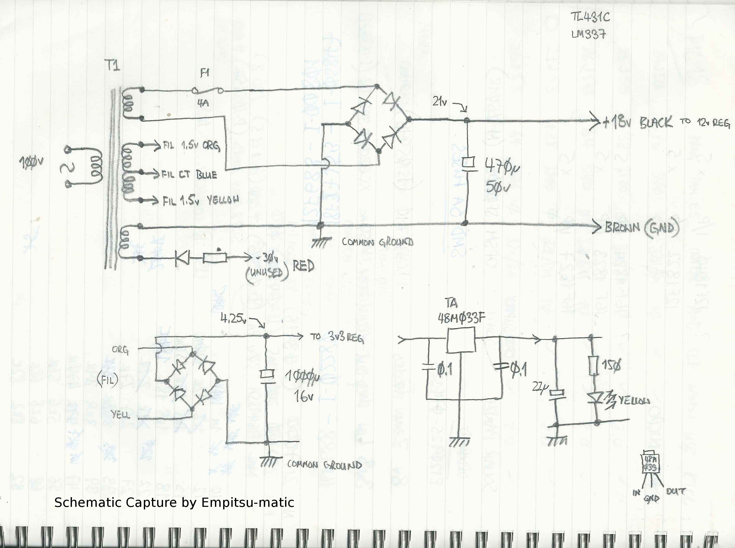
PIC18F27J53 PSU

Temperature sensing is courtesy of a handfull of DS18S20 one-wire temperature sensors. Why the (fairly ancient) DS18S20? Because I have close to a metric ton of the dang things sitting in my spares box, gathering dust..

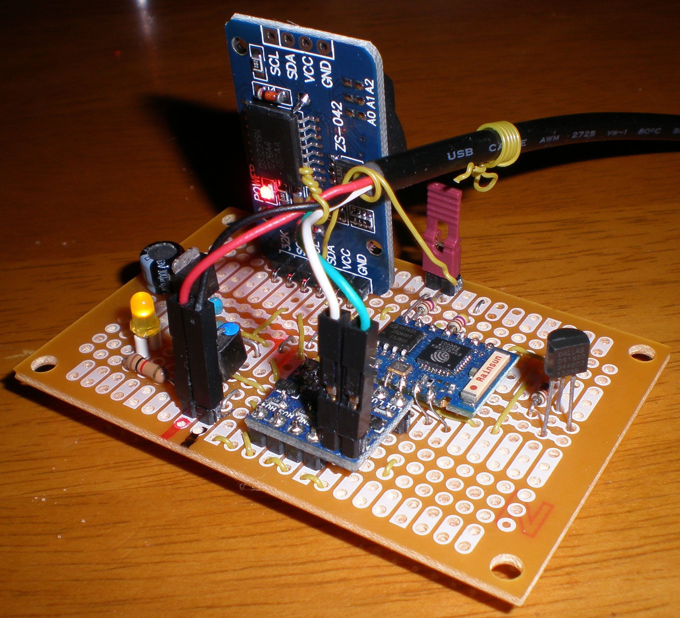
Communications between the remote sensors and the central microcontroller and button/display interfacing were going to be handled by a couple of satellite PICs talking to the master over an I2C bus (hence the daughter boards in the photograph). However, things have taken a turn (hopefully for the better) with the introduction of the ESP8266. I have a couple of ESP-03's and a couple of ESP-12's (and have wasted entirely too much time playing with these wonderful little gadgets) and now plan to put remote sensors and LCD displays on walls (which no longer have to be within a few centimetres of the PIC18) in rooms throughout the house.
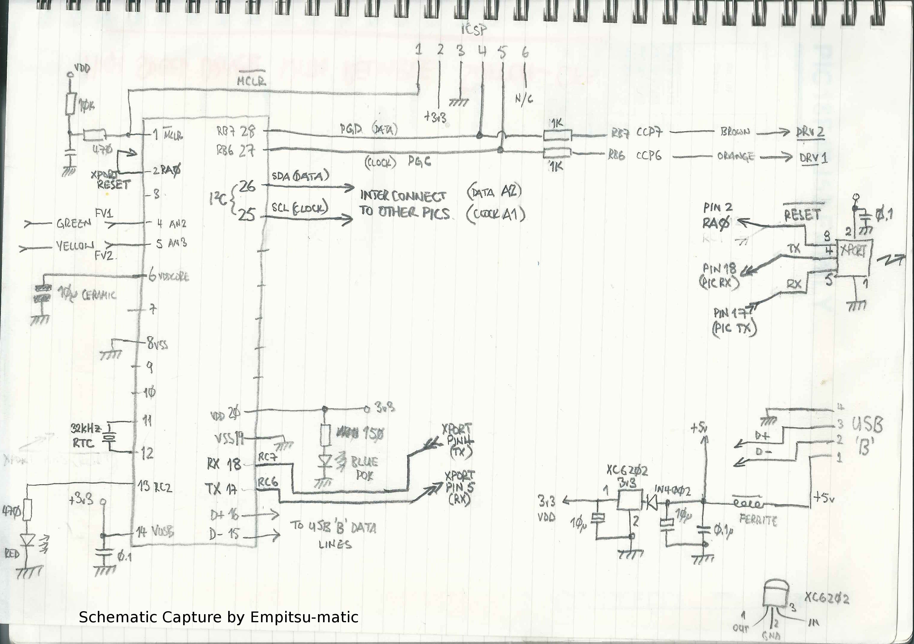
PIC18F27J53 Main Board Schematic

The PIC18 was, up until now, talking to the world via a Lantronix XPort (why? same story ...junk-box) even though it consumes a considerable chunk of power and heats the room almost as well as the woodstove. However, that too is due to be replaced with either another ESP8266, or a Wiz 5100 (I still rather favour the latter, as a hard-wired connection to the central PIC18 would be preferable and the Wiz 5100 compares very favourably to the ESP8266 in terms of power consumption when communications are active).

The PIC18F27J53 is nice in that it includes a RTC (as well as a ton of other peripherals and plenty of spare pins), so the idea is that it will have programmable on/off, high/low, normal/quiet settings (accessible via a web page) and also be capable of being overridden by the remote sensor/LCD units if someone wants an immediate blast of warm air, or prefers absolute silence to warmth.

The Software/Firmware:

The current firmware (such as it is) on the PIC18 was written using JALv2. I don't see too many projects on the web utilizing this much underrated language, but it is very, very useful (especially for the smaller PICs). It doesn't have the power, or complexity of C or C++, but it has a lot to recommend as a springboard for novice programmers. It is simple to use, easy to pick up, quick to compile and relatively forgiving in the syntax department. Although it also suffers from that simplicity (in that there are, for instance, no pointers), it does mean it has a very shallow learning curve and, generally speaking, all of the lessons learned when learning JAL will still apply when moving on to something a bit more complex. It is an ideal language people new to microcontrollers and to programming...

Read more »

  • 1 × PIC18F27J53 Another magic microcontroller from Microchip
  • 1 × Lantronix XPort [Deprecated] Will be replaced with the ESP8266 and Wiz5200 modules

  • A different direction...

    sbi.gaijin06/05/2015 at 14:14 0 comments

    As mentioned (briefly) in a previous log, I was (note the use of the past tense there!) impressed with the new kid on the block, the ESP8266 and had hatched a cunning plan to use a bunch of them as remote temperature sensors and room thermostats for this project. However, as anyone who has touched an ESP will already know by now, these neat little devices also have an additional feature ...a built in worm-hole which sucks all of the time out of your life space and tunnels it into a black hole in a parallel universe (same place as all of those odd socks end up!). Trying to do anything with these modules can take the odd couple of centuries (and at the end of that time, you might just end up with someone else's odd sock, rather than a functioning ESP).

    Recently I've been trying to get the I2C interface to work between an ESP and a DS3231 RTC module (the el-cheapo, middle kingdom version, with the AT24C32 memory chip on the same PCB). I have it on good authority that it works, as Richard Burton has spent a lot of time putting together libraries for both the DS3231 and the AT24C32 (and his blog is a pretty good read for anyone interested in the ESP). However, my attempts to get it to work ended with a pile of odd socks of unknown origin and nothing much else. <TL;DR> The short story is, if you want to use the I2C funtionality provided by the Espressif IoT SDK, you must call :-

    i2c_master_gpio_init()

    ...before doing anything else (and after having declared which GPIO pins you want to use as SDA and SCL). This call will set the GPIOs to "open drain" mode and then call the I2C initialize routine before returning. [The long, Hackaday-fail-of-the-week style story is here, if you're interested, BTW]

    Okay, so finally I have I2C working and can talk to the DS3231. As I already mentioned in the main project description, the master microcontroller, the PIC18F27J53 already has a RTC (one of the reasons it was chosen for this project to begin with), so why would I need another? Well, the DS3231 has a couple of very neat properties. One is that it has an on-chip temperature sensor (to adjust the internal oscillator for ambient temperature variations) which is not only fairly accurate, but also easy to read (integer part of the temperature in one byte and the fractional part in two bits of the next byte). It (the DS3231) also has a very versatile alarm setting, allowing easy configuration of repeatable alarms for a wide range of time periods with (importantly) an open-drain output for the alarm output.

    Additionally, the alarms and alarm output are both still available when the DS3231 is running from the back-up, coin-cell battery. What all of this means is that we can now use the combined ESP8266 + DS3231 module as a standalone, battery-powered temperature sensor or thermostat module, with the main battery only powering the ESP when woken by the alarm from the DS3231. This should, in theory anyway, get us past the main bugbear of the ESP, its fairly massive current consumption when active.

    We have at least two options for this mode of operation. The first is to use the DS3231 alarm as an interrupt on the ESP reset pin (instead of connecting it to GPIO16 for normal deep-sleep interrupts) and the second. more interesting one, to use the DS3231 alarm line to control the gate of a small P-channel MOSFET to switch VCC to the ESP, for a very nearly zero current "sleep".

    Stay tuned to find out which of these methods turns out to be the most effective (with the next update due in about, oh, three and a half odd socks).

  • ESP8266-ESP12 Eagle Part

    sbi.gaijin05/14/2015 at 00:39 0 comments

    Just added in an Eagle library file for the ESP-12 with the infamous GPIO04 and GPIO05 pin-swap problem corrected. I don't have an actual, physical PCB with this part mounted on it yet, so double check the library if you order any boards before I do (I'm a little bit worried that the pad lands may not be wide enough for easy, manual soldering). Updates welcome!

  • Jaluino Bee v2

    sbi.gaijin05/01/2015 at 00:36 0 comments

    Hardware iterations:

    Once you get your prototype hardware kinda' running, you suddenly find yourself with the issue of carrying on development without breaking what you already have. For software this is relatively easy, use CVS, git or whatever your preferred method of source code control is. For hardware, you pretty much need to have a second unit available so that you can continue to use rev-1 while still developing on rev-1A. This is all fine and dandy when you've cast your design in stone and had PCBs produced, but becomes a little more time consuming when everything is still on stripboard. So, I cheated again...

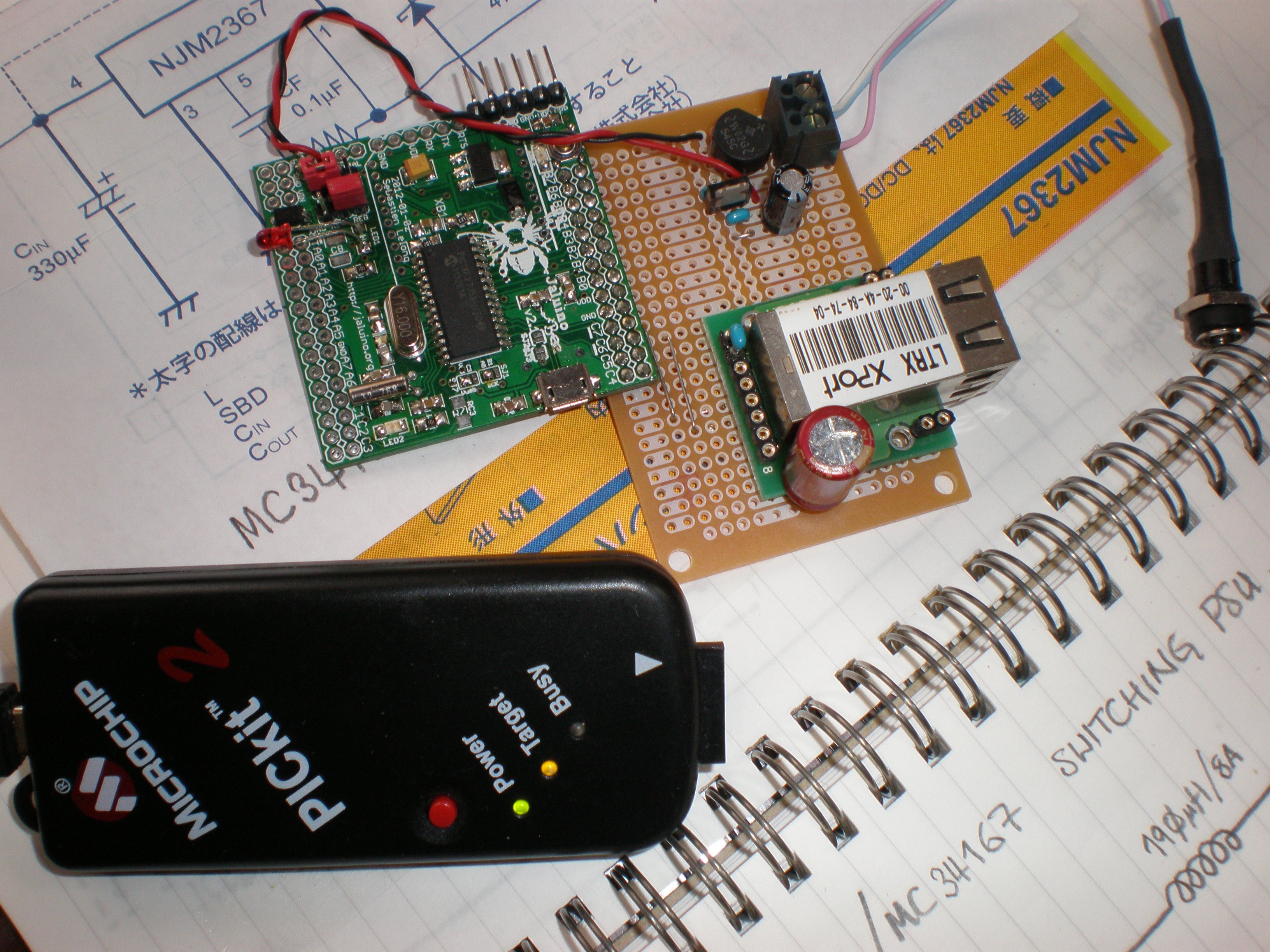
    A while back, [Seb] of the JALLIB group, very kindly sent me a JALuino Bee v2 board for evaluation (it's a great little board and a wonderful advertisement for JALv2 and JALLIB) which I'd played with, but hadn't really put to any good use yet. The part of this project which I was stumbling over at the time was the XPort implementation (and trying to get a simple, "curses" like library working), so I pressed the "Bee" board into use as a development system, cobbled together with yet another stripboard with the actual XPort and voltage regulator on-board.

    It may look a little Heath Robinson, but it works fine and saved me a ton of time over building another complete PIC18 main board. Thanks again Sebastien, the "Bee v2" rocks!

  • The ESP8266

    sbi.gaijin04/29/2015 at 13:35 0 comments

    Everyone and his dog has heard of the ESP8266 by now (and if your dog hasn't, where has it been ...under a rock?). The price of the ESP8266 modules makes them pretty much irresistible to the hobby user. The fact that the documentation and API sucked so badly initially slowed most of us down for a while, but Espressif have done a reasonable job in addressing those issues, while the real, die-hard developers don't let minor problems like that slow them down anyway and have already created some really outstanding projects for the rest of us slowcoaches to build on (Sprite_tm's esphttpd, Tuanpmt's MQTT, Zeroday's LUA nodemcu are three great examples of projects which have helped countless other people to get a handle on the ESP8266).

    Of course I snagged a couple of ESP8266's fairly early on (I skipped the minimal-featured ESP-01 and went for the ESP-03 instead). I slapped them onto some stripboard (if you don't happen to have $50-worth of purple gift certificates, I can recommend the Sunhayato ICB-86), flashed them with something useful and started playing.

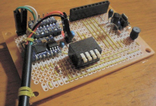
    An ESP8266 development board

    The board above has the ESP8266-03 module centre-left, a MOSFET voltage converter for the USB TX/RX lines directly above it, a 3v3 voltage regulator at the right-hand edge, a DS18S20 one-wire sensor over next to the regulator, a switch pack for setting the ESP into program mode and, at the top right, a connector for a Nokia 5110 LCD display.

    This little unit, along with Tuanpmt's MQTT project for the ESP, has me rethinking the whole heat-vent controller project. The low-end PICs with an I2C interface to the PIC18F have gone out of the window. The ESP board means we can now put the temperature sensors and the individual room sensor/display/control units way across the other side of the room, instead of needing to be positioned on the wall adjacent to the location of the PIC18F master (because of I2C bus length restrictions). We already have a couple of very low power mini-servers running round the clock (providing DHCP/DNS/NTP and web services) and now one of them is also running an MQTT server, too.

  • CVS Log to date.

    sbi.gaijin04/29/2015 at 07:49 0 comments

    The story so far, as told by the CVS log entries for main.jal:-

    RCS file: /store/CVS/Heat_Vent/PWM/main.jal,v

    Working file: main.jal

    head: 1.10

    branch:

    locks: strict

    access list:

    symbolic names:

    keyword substitution: kv

    total revisions: 10; selected revisions: 10

    description:

    ----------------------------

    revision 1.10

    date: 2014/01/01 11:40:13; author: cvsusers; state: Exp; lines: +9 -9

    Commented-out the USB defines and the few USB calls that were still left

    (now using XPort for I/O and debug messages).

    ----------------------------

    revision 1.9

    date: 2014/01/01 03:07:48; author: cvsusers; state: Exp; lines: +3 -2

    Added initialization of owbus_direction to "input".

    Changed OWSearchnTell() timing to once every 30 seconds (for testing).

    ----------------------------

    revision 1.8

    date: 2014/01/01 02:32:47; author: cvsusers; state: Exp; lines: +7 -7

    Changed OWDEBUG constant to a bit (from a byte) to use boolean logic (as

    it should have been from the start).

    ----------------------------

    revision 1.7

    date: 2013/02/28 22:53:46; author: cvsusers; state: Exp; lines: +25 -12

    Added small loop to trigger one-wire reads based on a settable minute

    count (from 1 to 255 minutes).

    ----------------------------

    revision 1.6

    date: 2013/02/26 21:51:35; author: cvsusers; state: Exp; lines: +27 -1

    Added in one-wire support.

    ----------------------------

    revision 1.5

    date: 2013/02/26 21:25:46; author: cvsusers; state: Exp; lines: +64 -35

    Updated to use dutycycle-ratio. Changed "PWM_lr" variable to "PWM_ratio" globally.

    Added a second timer slot to the interrupt-driven delay routine.

    Added a short routine to limit the number of PWM updates to a maximum of

    five per second to help stability.

    Updated omments in a few places.

    ----------------------------

    revision 1.4

    date: 2013/02/05 12:29:19; author: cvsusers; state: Exp; lines: +411 -39

    Added xport.jal and xport_defs.jal to support serial debug using the

    XPort module connected to the serial port lines.

    Minor change to voltage specifier in calc_table script.

    Added xport support to the Makefile.

    Added tons and tons and tons of changes to the main.jal file (because

    the CVS server was down for a couple of weeks) to support the XPort and to

    try adding PID (proportional, integrated and differential) control

    to the PWM/ADC feedback loop. Somewhat less than successful (the old

    method of using a set value depending on the output offset worked

    much more reliably).

    ----------------------------

    revision 1.3

    date: 2012/12/22 13:17:39; author: cvsusers; state: Exp; lines: +3 -1

    Added USB flush command into top of forever loop to ensure that

    the USB gets serviced on a regular basis.

    ----------------------------

    revision 1.2

    date: 2012/12/22 11:54:52; author: cvsusers; state: Exp; lines: +36 -29

    Updated to use "pwm6" instead of "pwm1" (valid PWM output on pin 27 now).

    Updated to initialize USB (unsuccessful).

    ----------------------------

    revision 1.1

    date: 2012/12/16 01:28:40; author: cvsusers; state: Exp;

    Simplified main.jal for testing PWM and ADC routines.

    =============================================================================

View all 5 project logs

Enjoy this project?

Share

Discussions

Similar Projects

Does this project spark your interest?

Become a member to follow this project and never miss any updates