 Radu Motisan
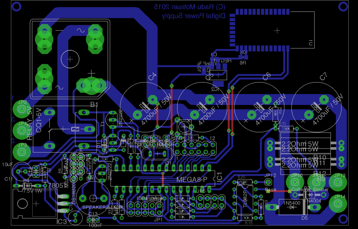
I was able to make a first PCB and write some of the code. The display now works and I can do the first tests. I decided to go with the PWM based DAC. The RC filter output is buffered with the first half of a TL082. The second half is used as a non-inverting amplifier and directly commands the bases of the 4 TIP3055 mounted in parallel on the heatsink. The transistors use equalising resistors of 0.1Ohm / 5W on each emitter.
I went with the TL082 because of its voltage ratings. Instead of a bipolar source, the plan is to have it hooked on ground and max voltage. It should work fine like that, because all I need is positive output .
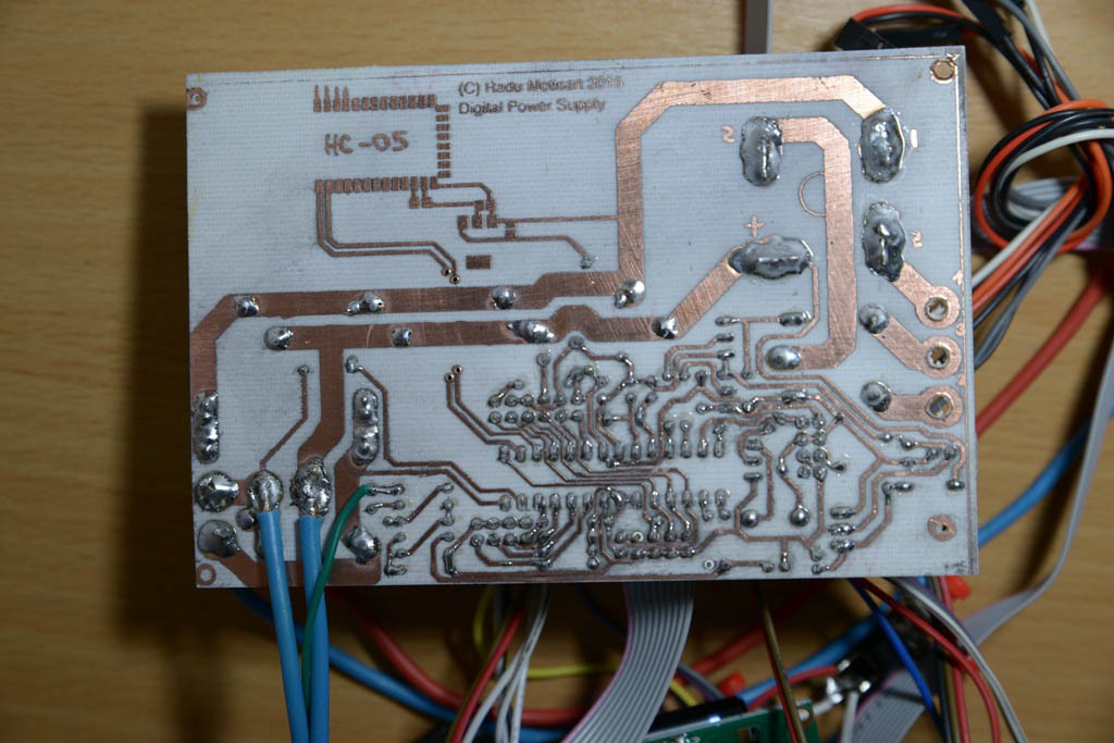
So, this will be an experiment: will it work or will it fry. I just broke my printer's cartridge, and with the last print I was able to do this PCB.
 |  |
I surely hope the shortcircuit answer will be fast enough. As for the laser printer cartridges, just a piece of advise for others: don't try cleaning the cylinders!
The electrolytics should be 50V, but I only had 35V in my toolbox. They're ok for the first tests. Here's the circuit so far:
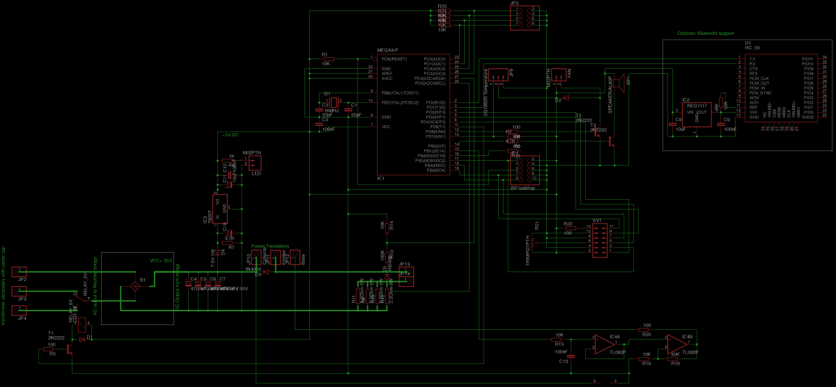 |  |
Discussions
Become a Hackaday.io Member
Create an account to leave a comment. Already have an account? Log In.