 Richard Deininger
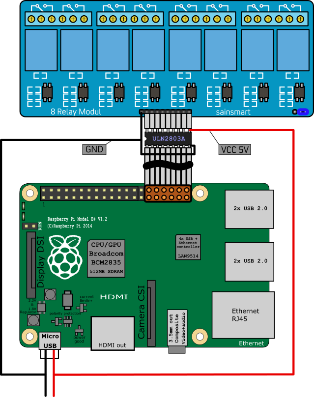
Since the Raspberry GPIO only support 3.3V and the Sainsmart relay module need 5V to switch the relay I used a ULN2803A and an external power supply (the same I use to power the Raspberry PI, since it supports more then enough amps) to operate the optical switches and protect the Raspberries GPIO.
To run a test on the whole thing I put together a small Python script.
Python Script:
import RPi.GPIO as gpio
import time
# peter ports = [6,12,13,19,16,26,20,21]

# port list
"""
#	GPIO-6  ==> relay 1
#	GPIO-12 ==> relay 2
#	GPIO-13 ==> relay 3
#	GPIO-19 ==> relay 4
#	GPIO-16 ==> relay 5
#	GPIO-26 ==> relay 6
#	GPIO-20 ==> relay 7
#	GPIO-21 ==> relay 8
"""
ports = [6,12,13,19,16,26,20,21]

#set pins to BCM mode
gpio.setmode(gpio.BCM)

#setup all pins for output
for port in ports:
 gpio.setup(port, gpio.OUT)


#set all pins to high (relay close NO, open NC)
print("high")
for port in ports:
 gpio.output(port, gpio.HIGH)


time.sleep(3)

#set alls pins to low (relay open NO, close NC)
print("low")
for port in ports:
	gpio.output(port, gpio.LOW)


# free gpio pins
gpio.cleanup()
Discussions
Become a Hackaday.io Member
Create an account to leave a comment. Already have an account? Log In.