So its been a little bit since my last update but I have been working hard. Lots of things to overcome. I wished to show the end product but of course there is growth to be had and I must learn a bit more to make it all work. let me show you a series of update pictures and explain them. Quickly..
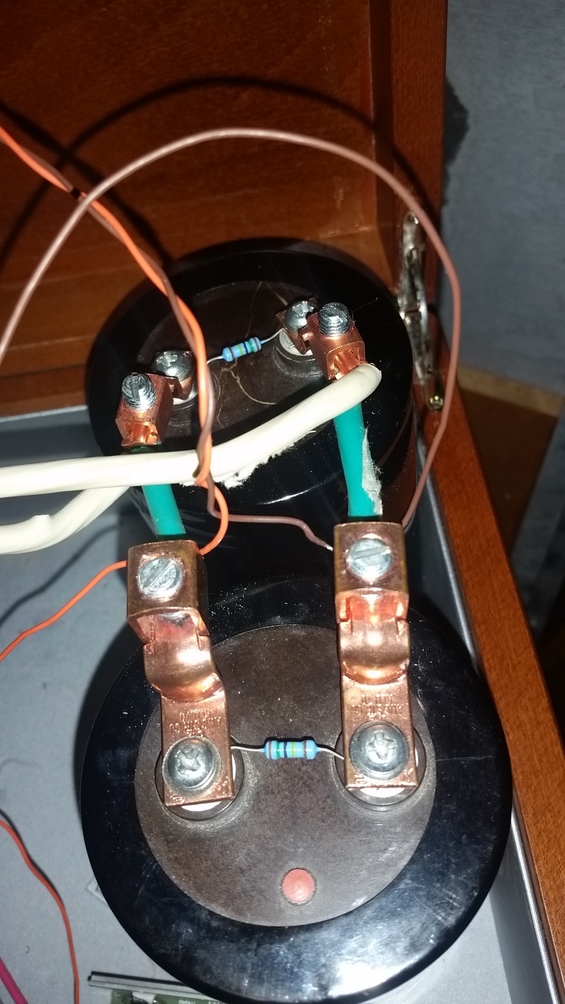
showing the small bleed resistor and mounting of two caps in parallel.
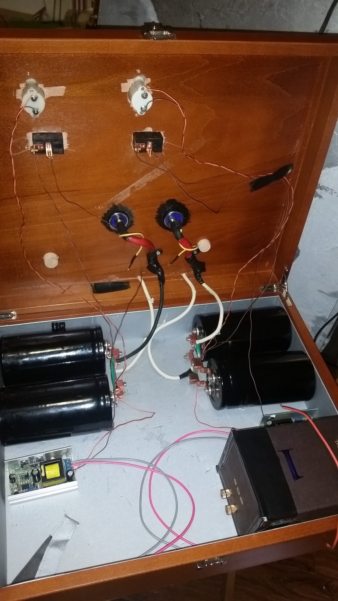
Beautiful new housing with the simple wiring needed without an Arduino.
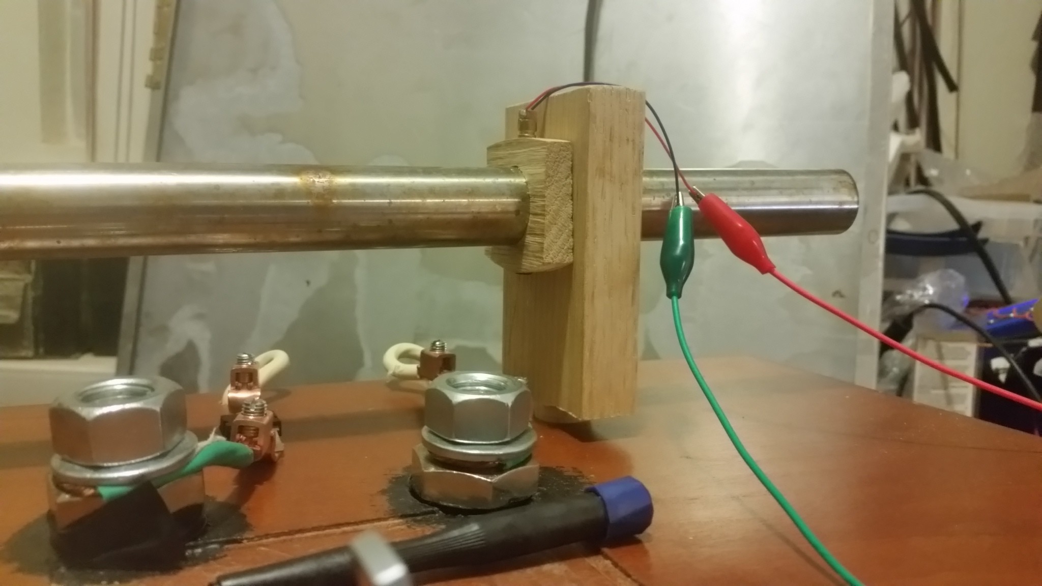
Showing how a laser can be powered in place.
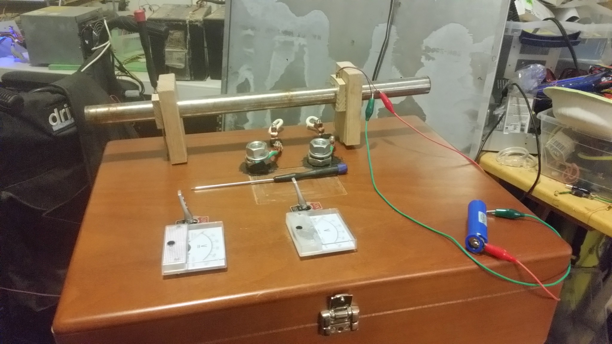
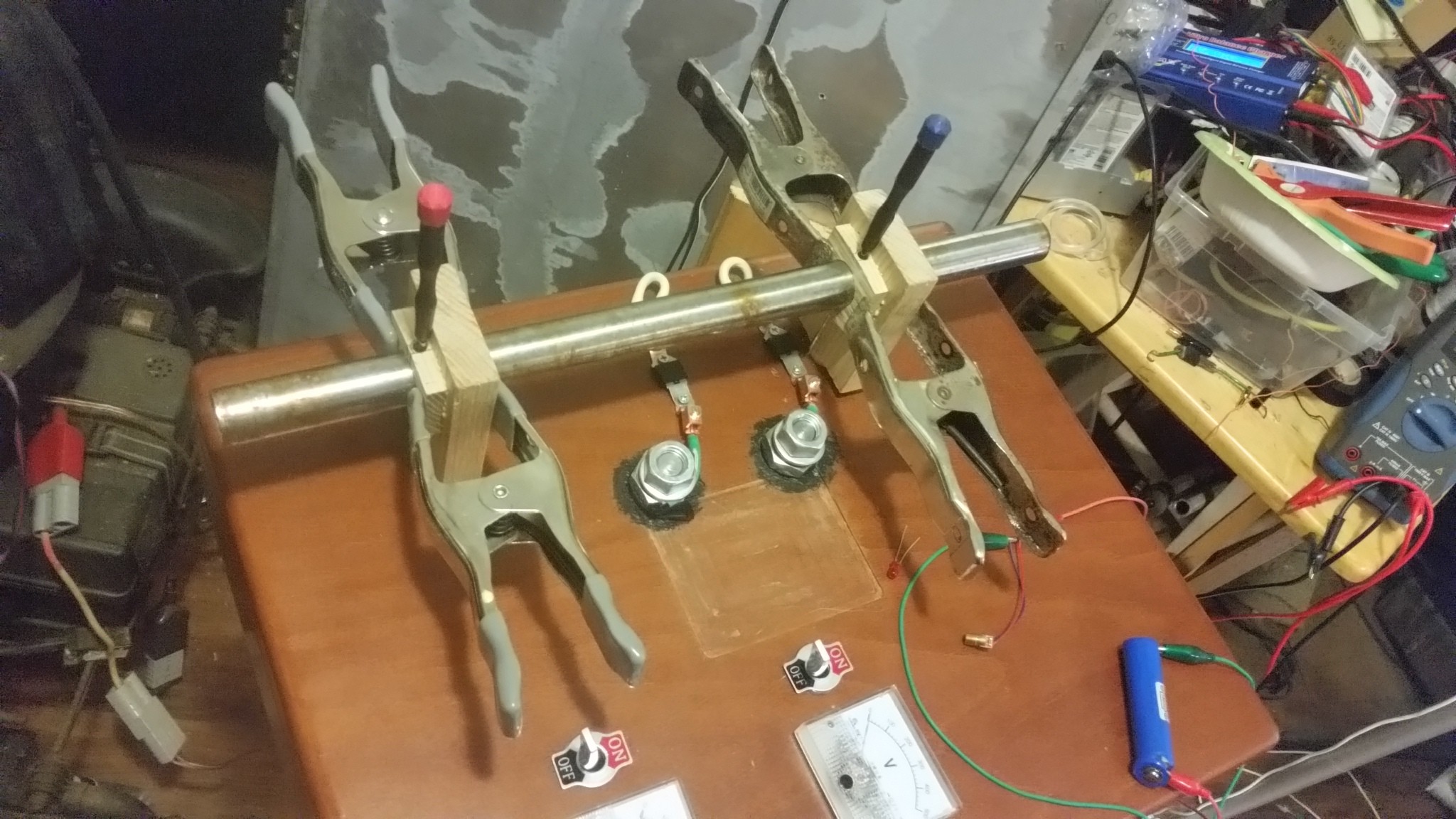
Shows the mounting of the small Jig needed to hold the laser and the LED to monitor the signal.
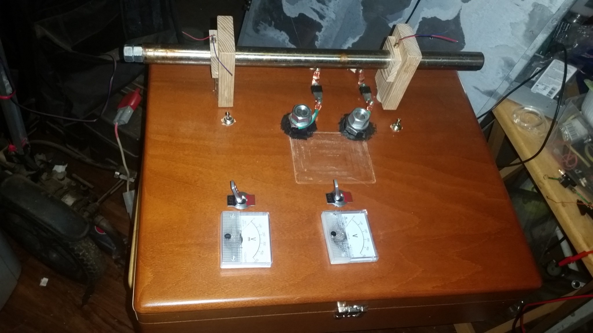
Nice surface layout showing the two charger voltage meters with on/off switches, the two Thyristors (SCRs) with their safety switches each.
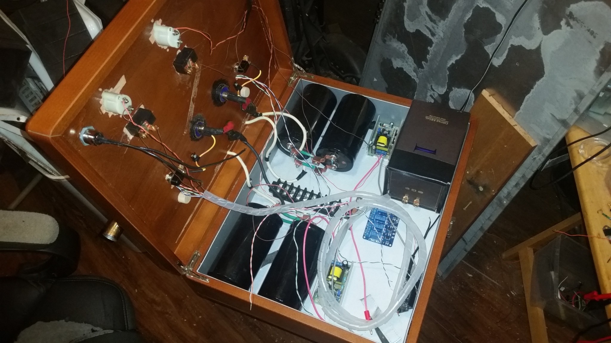
The daunting task of trying to manage these wires all over!
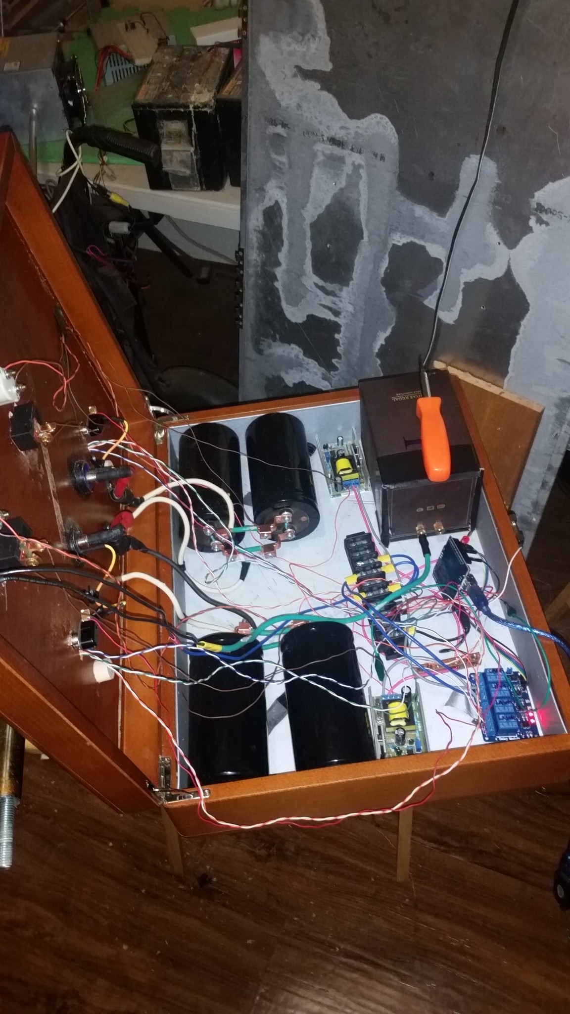
Initial close up
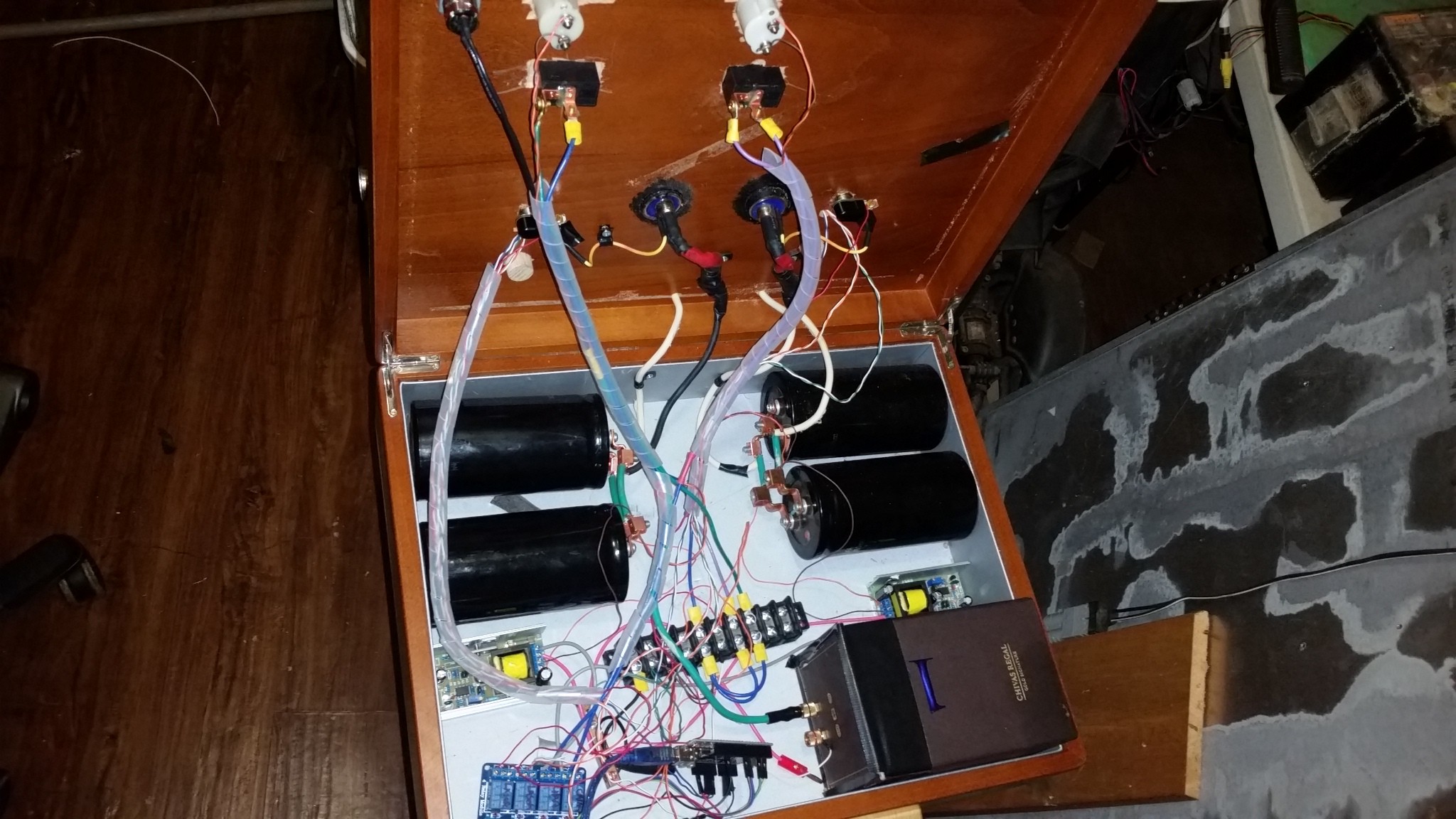
After some nice wire wraps to help.
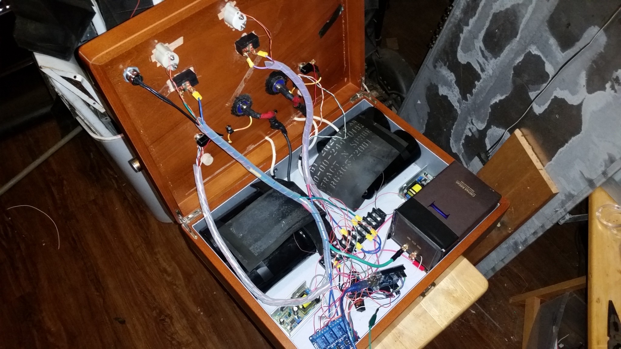
Added some High Insulation rubber shields to cover the HV Caps.
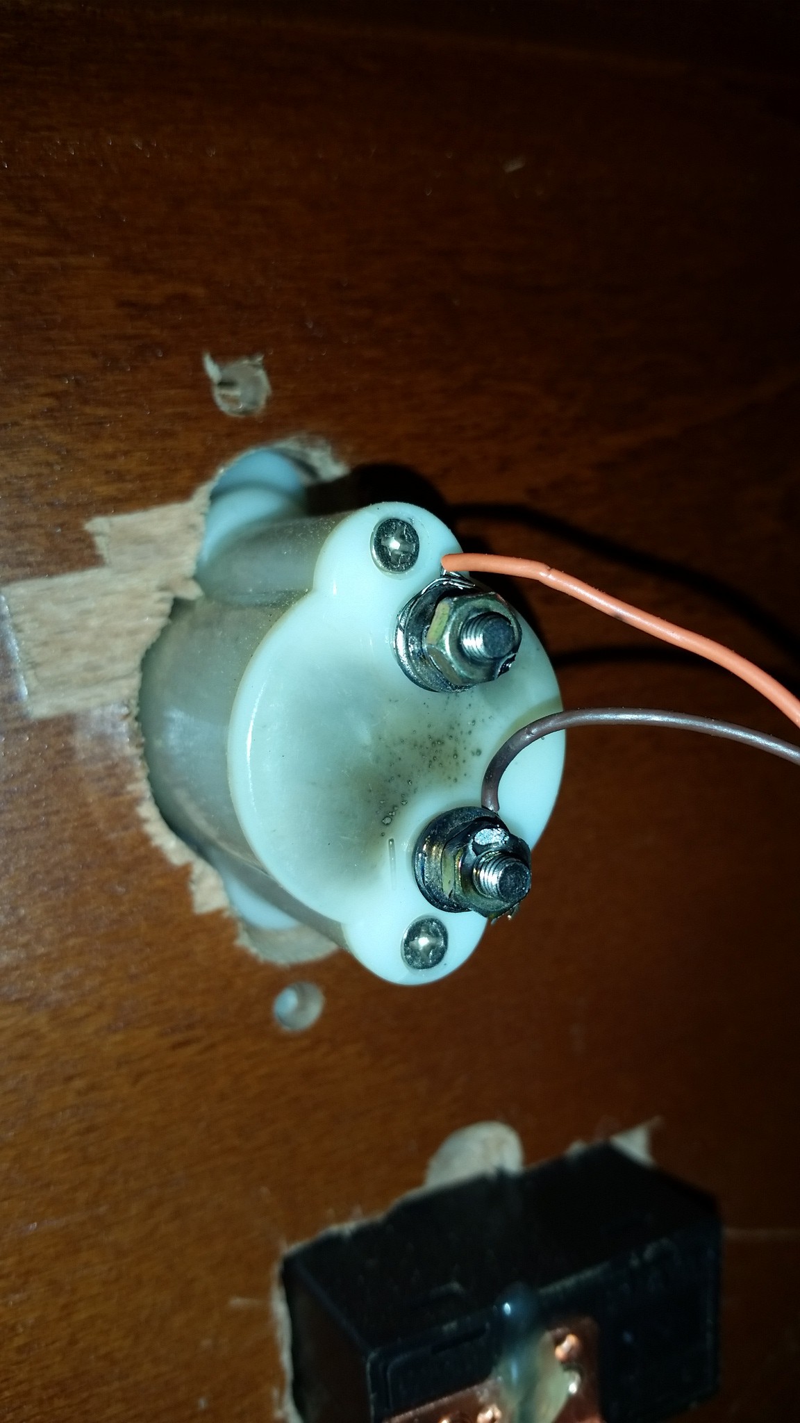
Here is where something shorted at a nice 250v ack ack farads of amps and shit I'm going to sit back and reassess my design.... turns out the voltage divider to monitor the charge circuits was attached to the negative vs the positive of the volt meter. oops/ damn :(
The programing is coming along and is 95% there I will release when folks might actually help feedback on it. :)
 3dscuba
Discussions
Become a Hackaday.io Member
Create an account to leave a comment. Already have an account? Log In.